00196044-05 - sg x und x4i fse_en.pdf - 第387页
Twin Head Twin Head Axis Track Signals Axis Control S tudent Guide (FSE) SIPL ACE X Series and X4I Edition 01/2009 EN T win Head 387 9-30: Measurement setup of Twin head track signals w ith the axis test box NOTE: The ze…
Twin Head
Axis Control Twin Head Axis Track Signals
Student Guide (FSE) SIPLACE X Series and X4I
Twin Head Edition 01/2009 EN
386
9.6.3 Twin Head Axis Track Signals
The track signals play a greater role with the new drive concept for HF machines. They are responsible
for the exactly and precise positioning of the axes and are used as the only feedback signal in the closed-
loop control system, meaning that they have an important influence on the axis dynamics.
9.6.3.1 Measurement Setup
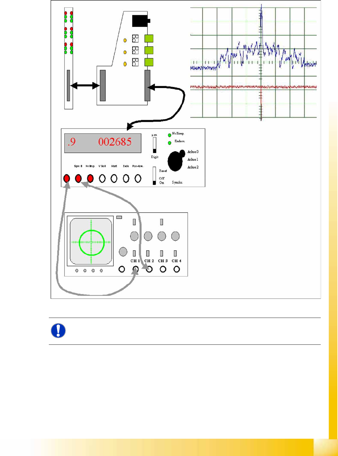
9-29: Measurement setup for the analog track signals of the Twin head Z axis
The analog track signals of the Twin head Z axes are counted by the incremental encoder.
NOTE:
The digital track signals for the Twin head can only be measured at the axis test box. The track
signals for the Twin head D-axis can only be measured as digital signals at the axis test box.
Twin Head
Twin Head Axis Track Signals Axis Control
Student Guide (FSE) SIPLACE X Series and X4I
Edition 01/2009 EN Twin Head
387
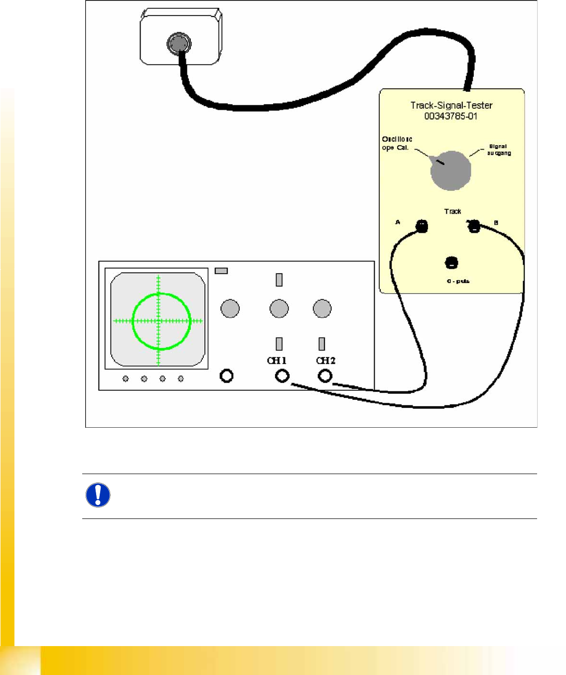
9-30: Measurement setup of Twin head track signals with the axis test box
NOTE:
The zero pulse measured at the axis test box has been reversed to become the zero pulse of
the Schmitt trigger circuit.
Twin Head
Axis Control Axis Control of Twin Head Z Axis
Student Guide (FSE) SIPLACE X Series and X4I
Twin Head Edition 01/2009 EN
388
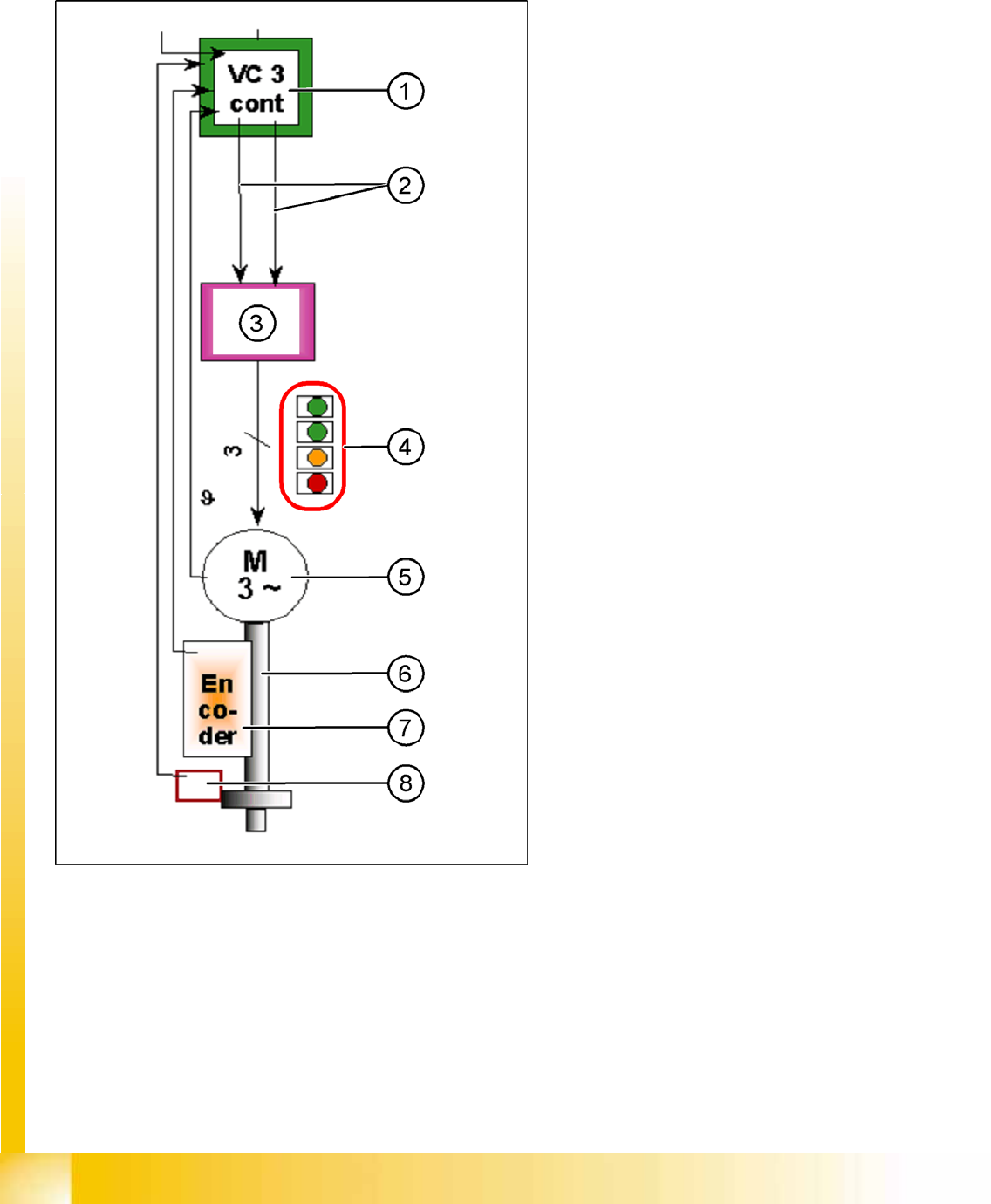
9.6.4 Axis Control of Twin Head Z Axis
The Z axis is driven by a 3-phase AC linear motor. The intermediate circuit voltage is 60 V (for high force
Twin head 120 V). Axis control is via 2 control signals from the VC3 controller (phase shift 120°) I nom
"W" and I nom "U". The third phase is generated at the servo amplifier.
9-31: Axis control Twin head Z axis
Legend
1. Axis controller board A363 with VC3 controller
(VC = Velocity Commutation)
2. Control signals
3. Servo amplifier
4. LEDs on servo board:
– Power supply ON
– Servo enable, if the enable signal has
been received from the axis board.
– Display R.M.S. current limiter shorter than
2.5 s.
– Error: overvoltage, overcurrent,
overtemperature longer than 2.5 sec.
5. 3-phase AC linear motor with integrated
temperature sensor.
6. Between the motor and the incremental scale
there is a fixed mechanical connection. The
incremental encoder is fixed to the Twin head
housing.
7. Incremental encoder: transmits the exact
position of the axis (track signals).
8. Force sensor
The servo board controls the 3-phase AC motor
directly.