00196044-05 - sg x und x4i fse_en.pdf - 第40页
Operational Safety Safety Instructions for Operating the Machine Safe ty Instructions for Moving the Component Trolley S tudent Guide (FSE) SI PL ACE X Series and X4I Operational Safety Edition 01/2009 EN 40 2.3.2.1 Safe…
Operational Safety
Safety Instructions for C&P20A Head Safety Instructions for Operating the Machine
Student Guide (FSE) SIPLACE X Series and X4I
Edition 01/2009 EN Operational Safety
39
2.3 Safety Instructions for Operating the Machine
2.3.1 Safety Instructions for C&P20A Head
2.3.2 Safety Instructions for the Twin Head
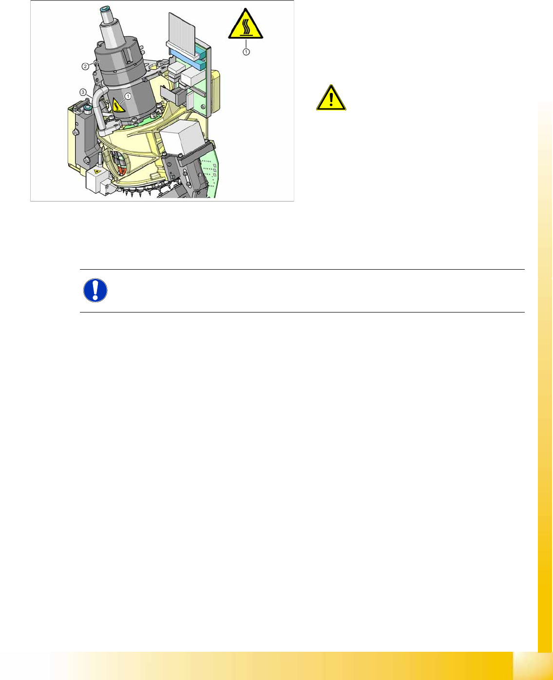
2-15: High temperatures on C&P20A head during continuous operation
Temperature warning label for C&P20A
head
1. Temperature information label [03031926-01]
2. Star motor housing
3. Handle
ATTENTION: HIGH TEMPERATURES
The star motor housing and the handle
on the placement head can develop
high surface temperatures during
continuous operation or when the
ambient temperature exceeds 22° C.
Take care when touching parts.
NOTE: Twin Head
Twin Heads are not used on X4I machines.
Operational Safety
Safety Instructions for Operating the Machine Safety Instructions for Moving the Component Trolley
Student Guide (FSE) SIPLACE X Series and X4I
Operational Safety Edition 01/2009 EN
40
2.3.2.1 Safety Instructions for Manual Movement of Z Axis on Twin Head
2.3.2.2 Safety Instructions for Twin Head Vision Modules
2.3.3 Safety Instructions for Moving the Component Trolley
X Always hold the handles with both hands when you want to move the component trolley.
X Remember that a component trolley with the full complement of feeder modules can tip over
sideways or forward on gradients of 20 or more.
X Make sure that the surface on which the trolley is moved has a significantly smaller gradient.
X Be careful not to collide with obstacles. The trolley could tip forward if it is traveling fast enough.
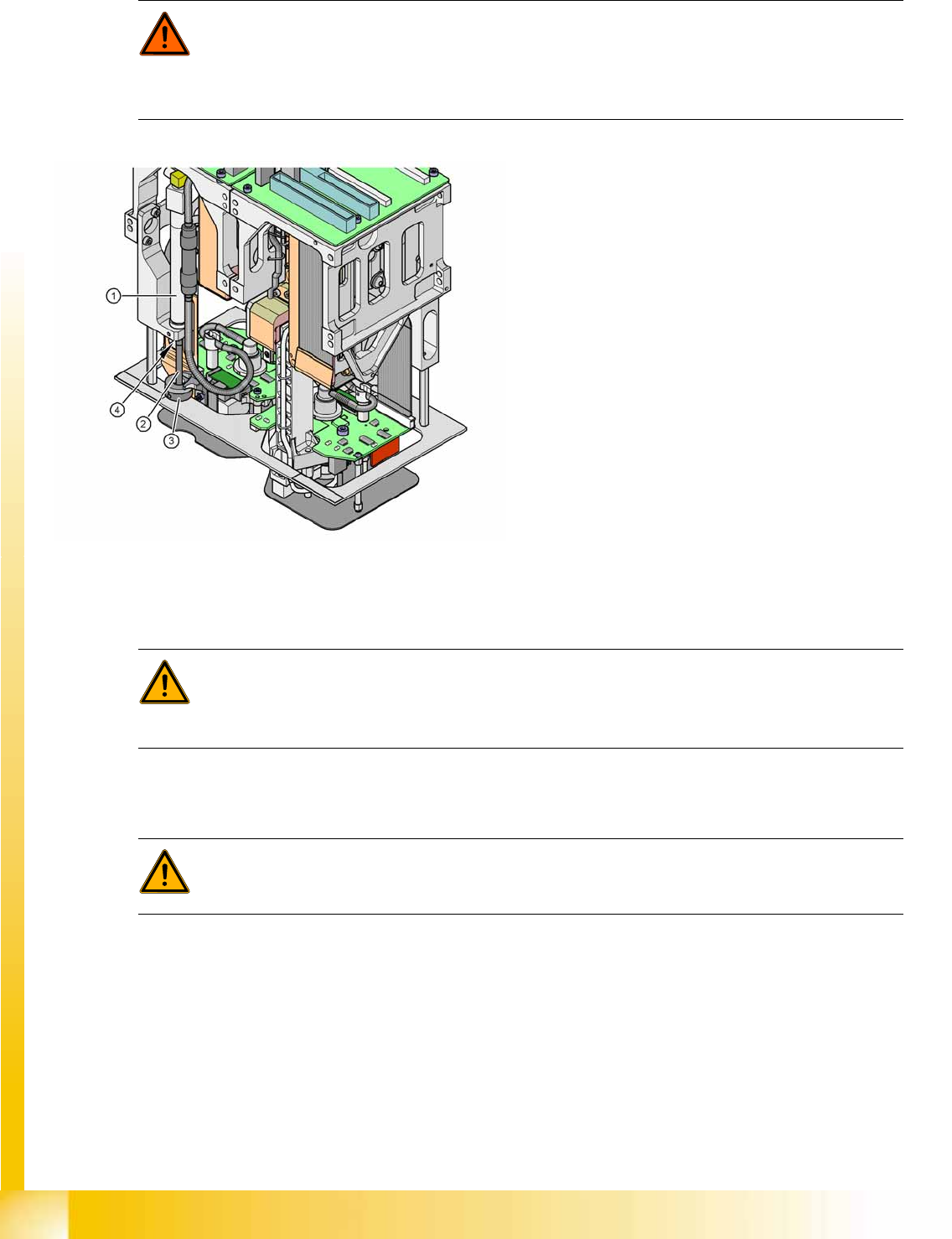
DANGER: DANGER OF CRUSHING ON Twin HEAD!
Never move the Z axis downwards by holding on to the return unit bumper. The strong spring
tension of the cylinder moves the bumper back very quickly and could injure your fingers. The
same warning applies to the inside of the Twin head, when the piston rod moves back to its
original position.
2-16: Risk of crushing by return unit on Twin head
Legend
1. Return unit, compressed air cylinder
2. Piston rod
3. Return unit bumper
4. Risk of crushing/trapping fingers
WARNING: Risk of head crash!
When changing the placement head from a Twin head to a C&P, you need to dismantle the fine
pitch and Flipchip Vision modules on the Twin head, otherwise the C&P will collide with the
module housings.
WARNING:
To prevent accidents, ALWAYS follow the rules listed below when you move the component
trolley.
Operational Safety
Switches and Buttons on the Placement Machine Safety Features
Student Guide (FSE) SIPLACE X Series and X4I
Edition 01/2009 EN Operational Safety
41
2.4 Safety Features
2.4.1 Switches and Buttons on the Placement Machine
2.4.1.1 Position of Switches and Buttons on the Placement Machine
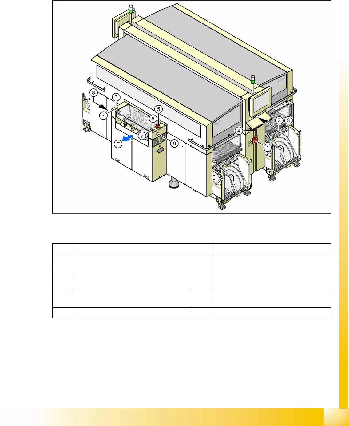
2-17: Position of switches and buttons - View of the PCB output side
Legend
1 Main switch 6 Start button (white) on the output side
2 Stop button (black) on the operator panel on the
power supply side
7 Stop button (white) on the output side
3 Start button (white) on the operator panel on the
power supply side
8 Button (black) for docking and undocking the
component trolley, location 2
4 Component counter on the operator panel on
the power supply side
9 Button (black) for docking and undocking the
component trolley, location 3
5 Emergency stop button on the output side T PCB transport direction