00196044-05 - sg x und x4i fse_en.pdf - 第407页
Component Handling Changeover Table with One Hand Operation - Functio n Changeover Table S tudent Guide (FSE) SIPL ACE X Series and X4I Edition 01/2009 EN Component Handling 407 10.1.3.3 Setting the Pneumatic Cy linder T…

Component Handling
Changeover Table Changeover Table with One Hand Operation - Function
Student Guide (FSE) SIPLACE X Series and X4I
Component Handling Edition 01/2009 EN
406
10.1.3.2 Undocking
To undock, make sure the compressed air is switched on and the protective cover is open (control
system off) and then press the button on the machine frame. The changeover table is released by the
feed device and is pushed out and lowered by two additional pneumatic cylinders, fixed to the left and
right of the empty tape duct. The COT electrical and pneumatic supply will be automatically disconnected
from the machine. When you press the button on X tables, the system first logs off all feeders in the
software. When machine is OFF:
When the machine is switched off or if there is no compressed air supply, the changeover table can be
easily pulled out of the machine by taking hold of the handles.
10-3: Centering pin and pneumatic cylinder at the left and right of the COT.
Legend
1. Centering Pin for the table plate
2. Cylinder pushing out the COT at undocking
Component Handling
Changeover Table with One Hand Operation - Function Changeover Table
Student Guide (FSE) SIPLACE X Series and X4I
Edition 01/2009 EN Component Handling
407
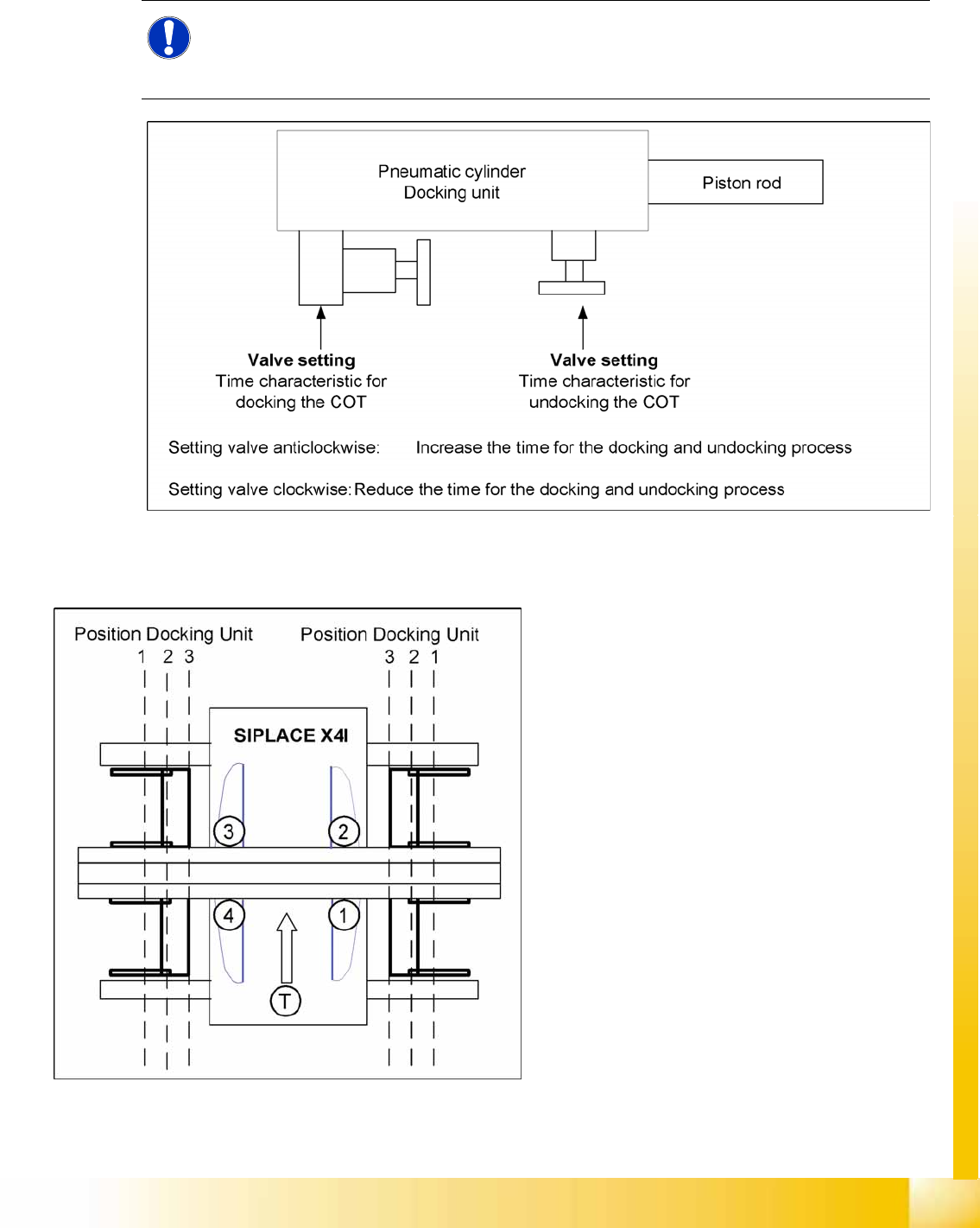
10.1.3.3 Setting the Pneumatic Cylinder
The movement of the cam disks at the docking unit can be individually set at the valves of the two
cylinders.
10-4: Setting the pneumatic cylinders at the docking unit
10.1.3.4 Positioning the Docking Unit in the Machine
NOTE:
When setting the pneumatic cylinders, make sure that the component trolley is pulled into the
docking unit parallel. The docking and undocking process of the changeover table should be set
to approx. 2 seconds.
10-5: Positioning the docking unit
SIPLACE X4I
1. Gantry 1
2. Gantry 2
3. Gantry 3
4. Gantry 4
T = transport direction
The docking units can be installed at three
different positions in the machine for each
location. The position of the docking unit depends
on the machine type and the head configuration.
Gantries 2 and 4 have been rotated in the
SIPLACE X4I machine. This means that the
docking units at all four locations are mounted in
position 3. This creates short travel ranges
between the feeders and the board.
Component Handling
Changeover Table Changeover Table with One Hand Operation - Function
Student Guide (FSE) SIPLACE X Series and X4I
Component Handling Edition 01/2009 EN
408
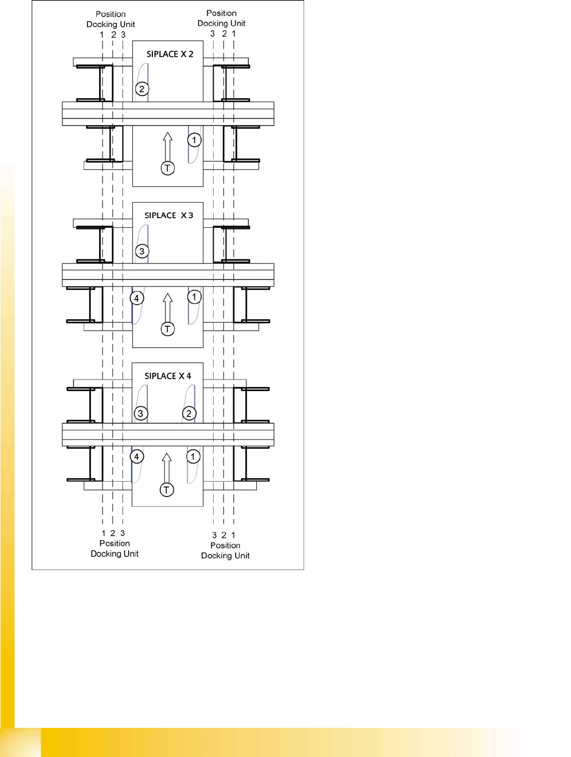
SIPLACE X2, X3 and X4
1. = Gantry 1
2. Gantry 2
3. Gantry 3
4. Gantry 4
T = transport direction
The docking unit of the MTC2 is always installed in
position 3 (see diagram).