00196044-05 - sg x und x4i fse_en.pdf - 第408页
Component Handling Changeover Table Changeover Table with One Hand Operation - Function S tudent Guide (FSE) SI PL ACE X Series and X4I Component Ha ndling Edition 01/2009 EN 408 SIPLACE X2, X3 and X4 1. = Gantry 1 2. Ga…
Component Handling
Changeover Table with One Hand Operation - Function Changeover Table
Student Guide (FSE) SIPLACE X Series and X4I
Edition 01/2009 EN Component Handling
407
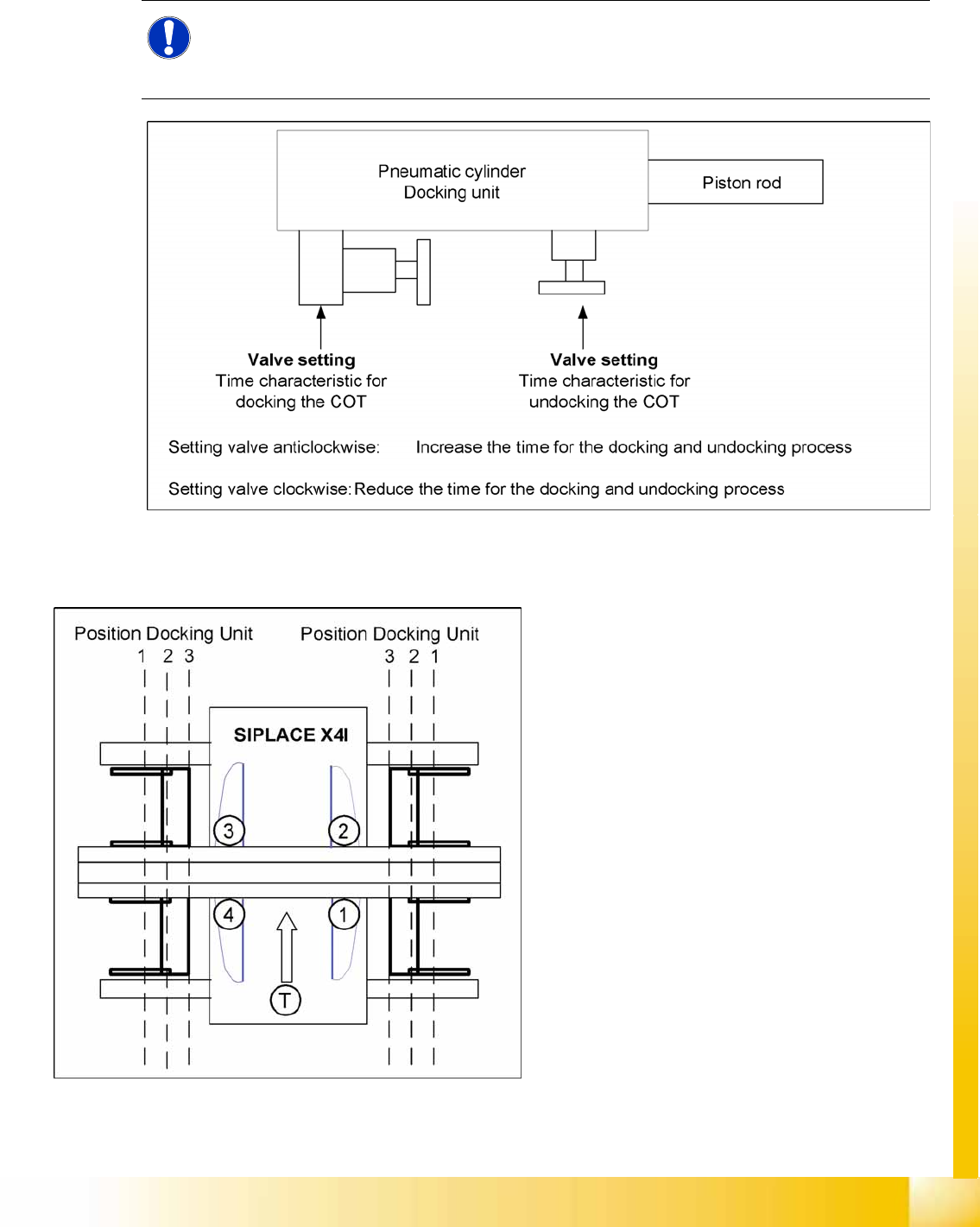
10.1.3.3 Setting the Pneumatic Cylinder
The movement of the cam disks at the docking unit can be individually set at the valves of the two
cylinders.
10-4: Setting the pneumatic cylinders at the docking unit
10.1.3.4 Positioning the Docking Unit in the Machine
NOTE:
When setting the pneumatic cylinders, make sure that the component trolley is pulled into the
docking unit parallel. The docking and undocking process of the changeover table should be set
to approx. 2 seconds.
10-5: Positioning the docking unit
SIPLACE X4I
1. Gantry 1
2. Gantry 2
3. Gantry 3
4. Gantry 4
T = transport direction
The docking units can be installed at three
different positions in the machine for each
location. The position of the docking unit depends
on the machine type and the head configuration.
Gantries 2 and 4 have been rotated in the
SIPLACE X4I machine. This means that the
docking units at all four locations are mounted in
position 3. This creates short travel ranges
between the feeders and the board.
Component Handling
Changeover Table Changeover Table with One Hand Operation - Function
Student Guide (FSE) SIPLACE X Series and X4I
Component Handling Edition 01/2009 EN
408
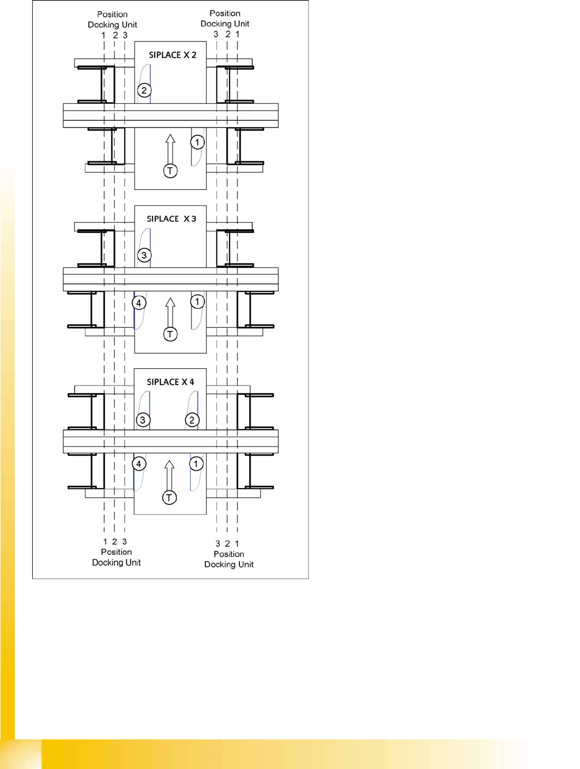
SIPLACE X2, X3 and X4
1. = Gantry 1
2. Gantry 2
3. Gantry 3
4. Gantry 4
T = transport direction
The docking unit of the MTC2 is always installed in
position 3 (see diagram).
Component Handling
Changeover Table with One Hand Operation - Function Changeover Table
Student Guide (FSE) SIPLACE X Series and X4I
Edition 01/2009 EN Component Handling
409
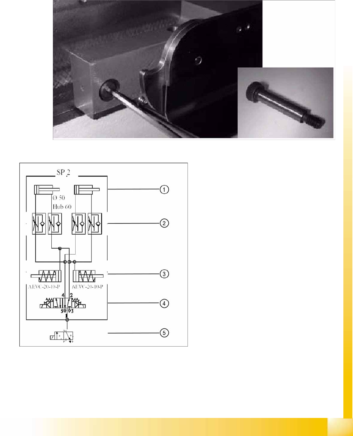
10.1.3.5 Fitting the Docking Unit
To guarantee the precise fit of the table feed device for accurate pickup of small components, the
docking unit on the inside of the machine is fixed with a special fitting screw. When fitting the docking
unit for the changeover table, make sure that this screw is fixed first, before the other screws.
10-6: Special fitting screw on the changeover table docking unit
10-7: Pneumatic diagram docking unit
Legend
1. Pneumatic cylinder for moving the cam disks.
This means that the changeover table plate
will move 43mm horizontally and 20 mm
vertically into the machine.
2. Throttle valves for adjusting the speed of the
pneumatic cylinders (time adjustment).
Adjustment is made without the changeover
table and should take approx. 2 seconds for
docking and undocking.
3. Pneumatic cylinders for ejecting the COT
during the undocking procedure.
4. 5/2 way valve for controlling the pneumatic
cylinder.
5. Safety valve in case of electrical faults