00196044-05 - sg x und x4i fse_en.pdf - 第411页
Component Handling Optional Extension on the Changeover Tables Changeover Table S tudent Guide (FSE) SIPL ACE X Series and X4I Edition 01/2009 EN Component Handling 41 1 10.1.5 Optional Extension on the Changeover T able…
Component Handling
Changeover Table Setting the COT Height
Student Guide (FSE) SIPLACE X Series and X4I
Component Handling Edition 01/2009 EN
410
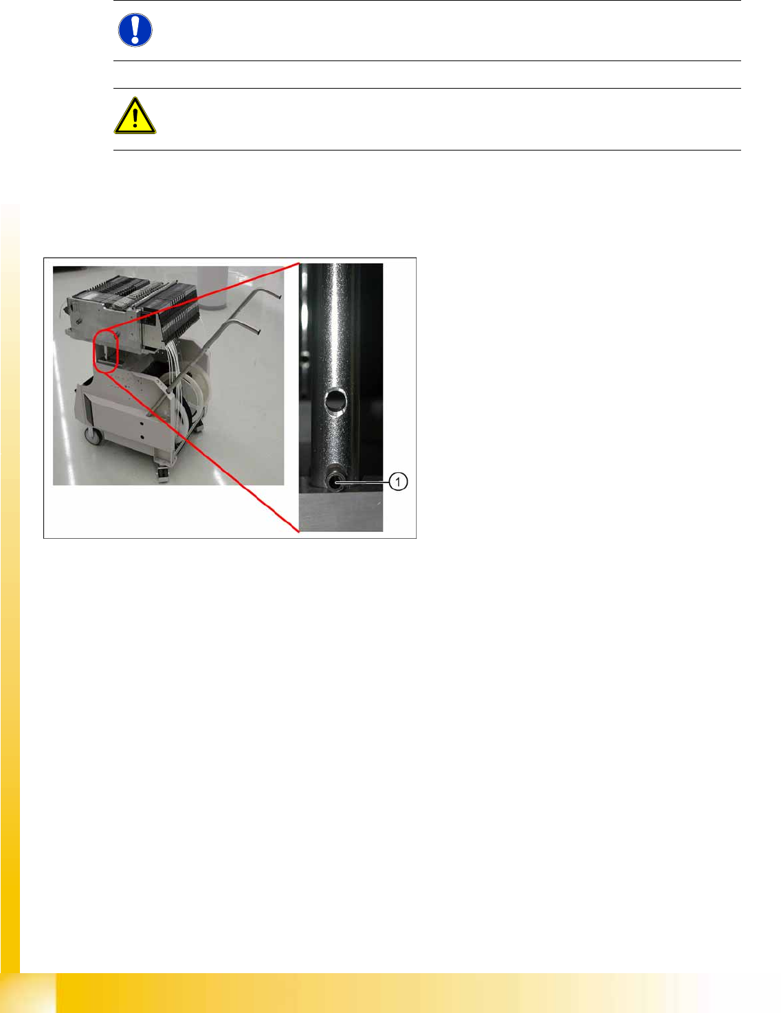
10.1.4 Setting the COT Height
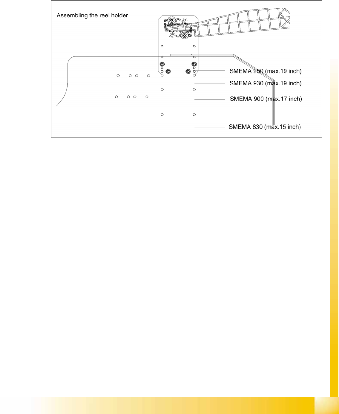
The changeover table can be adjusted to any height between 830 and 950 mm by removing the two pins
from the hollow shafts, which hold the table plate.
10.1.4.1 X Table
10.1.4.2 Increasing and Reducing the COT Height
X Fix the screwed eyelet in the center of the table plate.
X A second person should lift the aluminum plate for X tables.
X Raise the changeover table plate slightly and knock the pins out of the left and right hollow shafts.
X Move the table plate to the correct height.
X Put back the 2 cotter pins (2) into the drilling hole of the sleeve shaft.
X Now, COT height is adjusted.
NOTE:
Adjustment of the COT height is in general identical for S and X tables.
CAUTION:
Always use the screwed eyelet to fix the table plate, irrespective of whether you want to raise or
lower the component trolley.
10-8: X table - adjusting the machine height
Legend
1. Hole for the cotter pins
Component Handling
Optional Extension on the Changeover Tables Changeover Table
Student Guide (FSE) SIPLACE X Series and X4I
Edition 01/2009 EN Component Handling
411
10.1.5 Optional Extension on the Changeover Tables
10.1.5.1 Additional Reel Holder of the X Table
The X table has 40 feeder locations. However, the tape reel container can only accommodate 30 tape
reels. An additional tape reel holder is therefore provided for the X table, as an option.
10-9: Additional reel holder X table
Component Handling
X Feeder General
Student Guide (FSE) SIPLACE X Series and X4I
Component Handling Edition 01/2009 EN
412
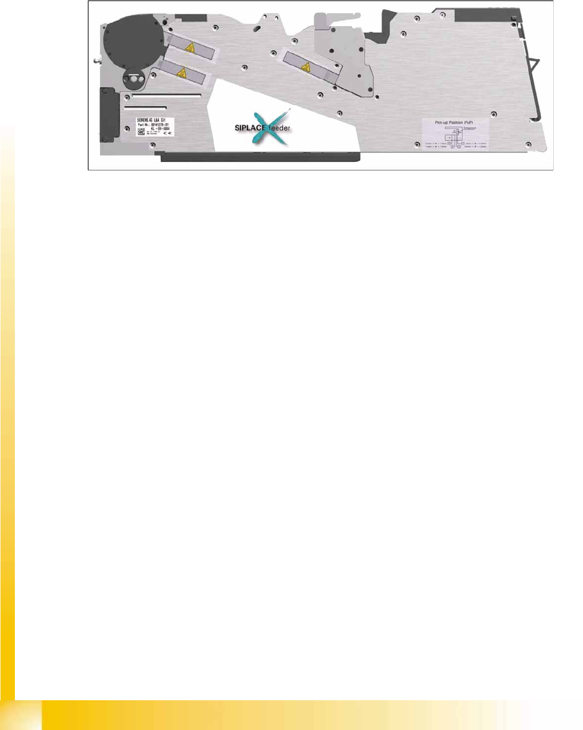
10.2 X Feeder
10.2.1 General
10-10: X feeder - basic view
Performance :
Increased demand for speed at C&P20A head (Communication, dynamics 40ms for 4mm), Feeder
should not limit placement (communication, transport)
Precision :
Designed for smallest components currently on the market
Reliability:
Reliable drive system, "Closed loop" drive regulation, new mechanical interface, new electrical interface,
brushless DC motors, optimized gear
Flexibility :
Different pitches adjustable, "Hot swapping" possible, upgrade per firmware download possible with
station software, adaptable for "problematic tapes", free step width, variable speed profiles
Usability :
Single track feeder, Tape loading, Interface to operator, Integrated Splice recognition (optional), Able to
handle sticky tapes (optional PSA kit (pressure sensitive adhesive)), no connectors and cables, operator
panel
Intelligence :
Unique feeder- ID, Management data (cycles, power up hours, errors,...), Object data are stored in set-
up control data base
Robustness :
No "on mechanical end stops" --> controlled movement of the transport