00196044-05 - sg x und x4i fse_en.pdf - 第45页
Operational Safety Safety and Signaling Circuit Safety Features S tudent Guide (FSE) SIPL ACE X Series and X4I Edition 01/2009 EN Operational Safety 45 2.4.3 Safety and Signaling Circuit 2.4.3.1 Safety Circuit Function T…
Operational Safety
Safety Features Position of Pushbutton for Docking and Undocking the Component Trolley
Student Guide (FSE) SIPLACE X Series and X4I
Operational Safety Edition 01/2009 EN
44
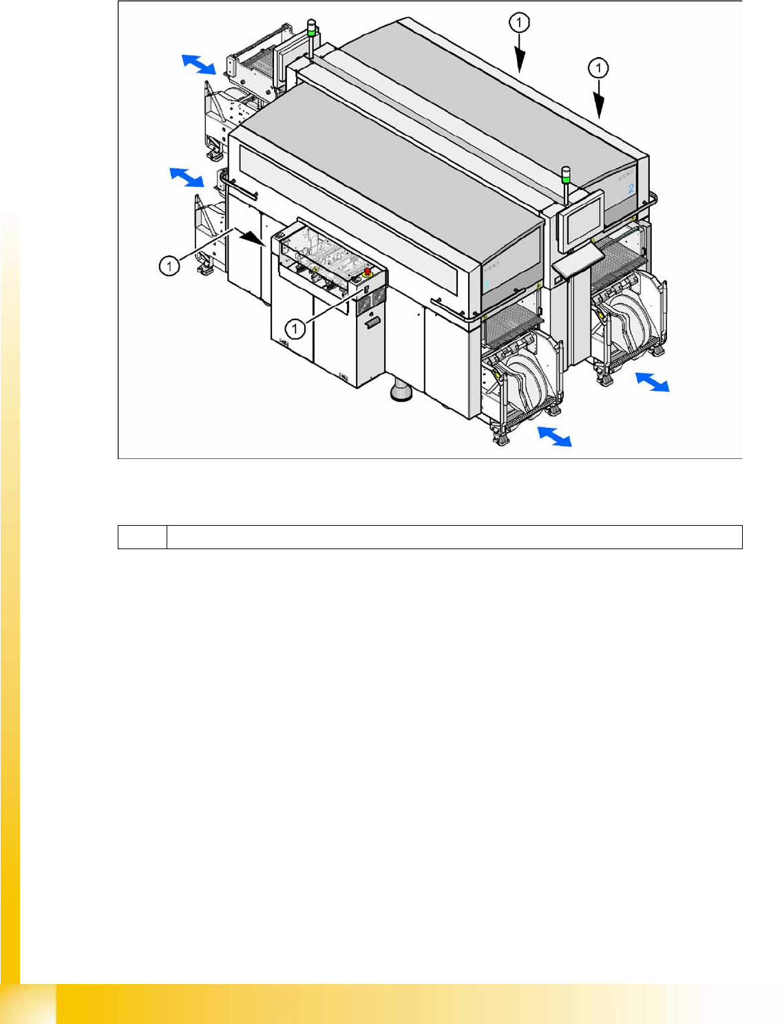
2.4.2 Position of Pushbutton for Docking and Undocking the Component Trolley
2-19: Pushbutton for docking and undocking the component trolley
Legend
1 Pushbutton for docking and undocking the component trolley

Operational Safety
Safety and Signaling Circuit Safety Features
Student Guide (FSE) SIPLACE X Series and X4I
Edition 01/2009 EN Operational Safety
45
2.4.3 Safety and Signaling Circuit
2.4.3.1 Safety Circuit Function
The following conditions must be fulfilled in order to start and operate the placement machine:
All four component trolleys must be docked in and connected.
All protective covers must be closed.
The two cover flaps over the PCB conveyor must be closed.
Both emergency stop buttons must be released.
The cover flaps (option) over the feeder modules must be closed.
The minimum operating pressure must have been reached.
The "software enable" signal must be active. This ensures that the safety circuit is closed.
The power supply must be sending 24 V to the Start buttons and the protective contactor
combination.
If one of the Start buttons is now pressed, the protective contactor combination SSK K6 will switch
and activate the following components:
– 250 VDC intermediate circuit voltage for the servo amplifiers for the gantry axes
– 145 VDC intermediate circuit voltage for the star axes
– The axis unit receives a "servo enable" signal for the servo amplifier
– 48 V for X tables (34 V for S tables, not for X4I) – operating voltage is switched through to
component trolleys
– 24 VDC operating voltage is switched to the used tape cutters.
– The PCB conveyor control receives the enable signal for the PCB clamping, the PCB stopper
and the lifting table control.
The machine is then ready for use.
Operational Safety
Safety Features Safety and Signaling Circuit
Student Guide (FSE) SIPLACE X Series and X4I
Operational Safety Edition 01/2009 EN
46
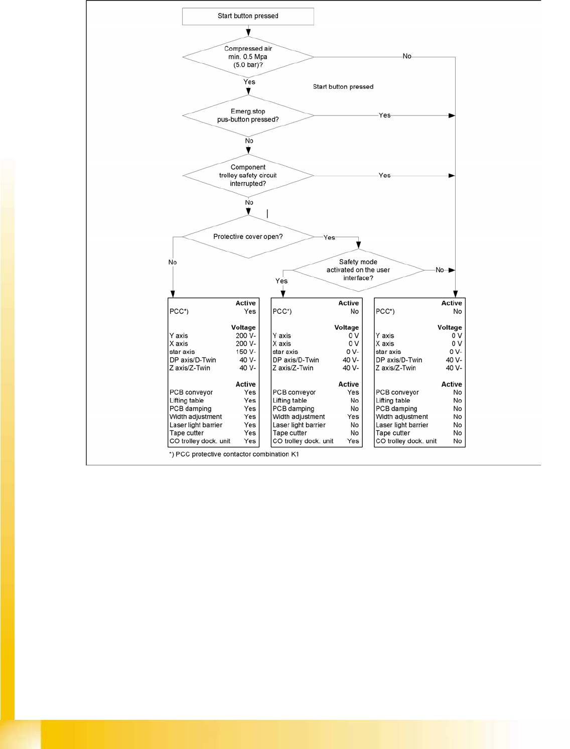
2.4.3.2 Safety Loops
2-20: Safety Loops