00196044-05 - sg x und x4i fse_en.pdf - 第455页
Modular Conveyor Width Adjustment Unit Conveyor Settings S tudent Guide (FSE) SIPL ACE X Series and X4I Edition 01/2009 EN Modular Conveyor 455 1 1.3.3 Wid th Adjustment Unit 1 1.3.3.1 Setting the Proximity Switch on the…
Modular Conveyor
Conveyor Settings Setting the Fixed Conveyor Side (from SW701)
Student Guide (FSE) SIPLACE X Series and X4I
Modular Conveyor Edition 01/2009 EN
454
Legend
After teaching the fixed conveyor side, you need to recalibrate the PCB reference corner, to prevent
fiducial errors during placement.
11.3.2.2 Connecting the Dual Conveyor Lifting Tables
X Remove the lifting table plate on conveyor lane 2 in PA1 and on lane 1 in PA2.
X Loosen the lockscrew(s) (4) and use a screwdriver to push the hexagonal circlip over the shaft on
lifting table 1.
X Perform lifting table connection for all placement areas (arrangement rotated by 180°.)
X Configure the new conveyor mode in SIPLACE Pro
(1) Bearing flange – first version 12 mm (2) Bearing flange – new version 15 mm
NOTE:
The fixed conveyor side may only be adjusted via software and with the width adjustment
devices. This ensures that the conveyor sides are in their correct positions (parallel) i.e. that the
conveyor runs straight.
NOTE:
This option is a mechanical necessity when you use the dual conveyor as a single conveyor.
The two lifting tables move parallel when they are connected.
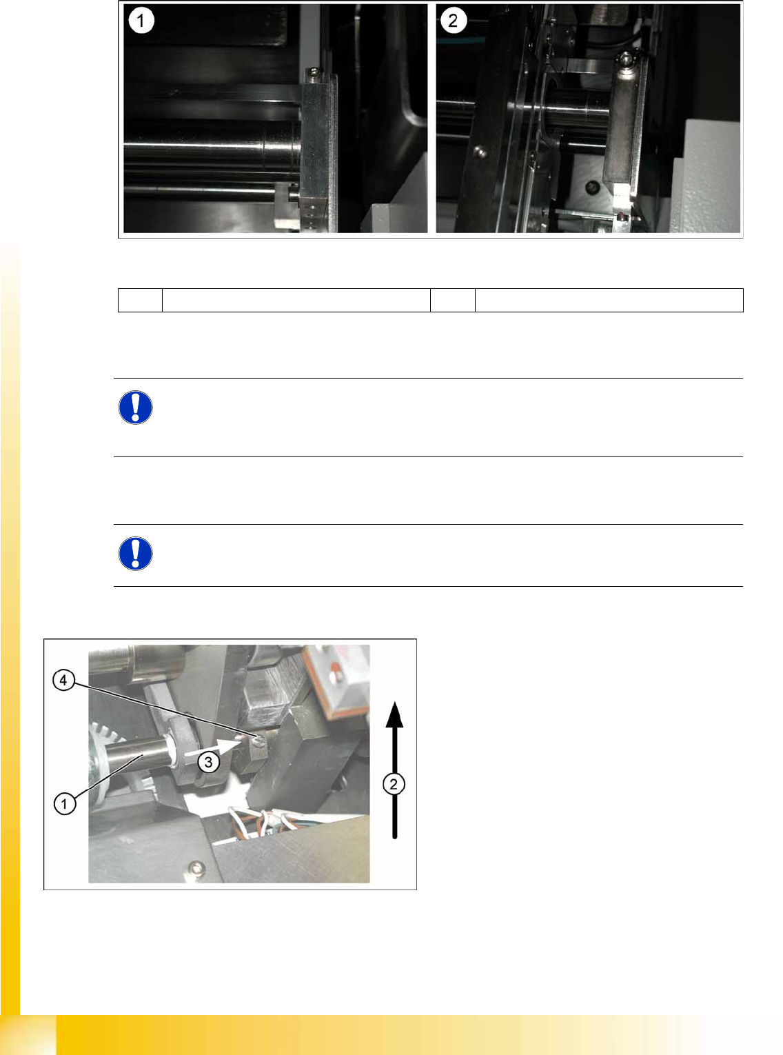
11-12: Lifting table
The drive shaft (1) is connected to the piston
rod of the pneumatic cylinder. This shaft
couple the second lifting table of the dual
conveyor. The lifting table drive shaft also has
an additional rod with a hexagonal circlip.
They secure the sleeve shaft in the desired
position.
Direction of transport (2).
Direction (3) in which the hollow shaft from
lifting table 2 (1 in PA 2) is to be moved to lifting
table 1 (2 in PA 2).
Lock screws (4).
Modular Conveyor
Width Adjustment Unit Conveyor Settings
Student Guide (FSE) SIPLACE X Series and X4I
Edition 01/2009 EN Modular Conveyor
455
11.3.3 Width Adjustment Unit
11.3.3.1 Setting the Proximity Switch on the Adjustment Unit
X When installing the proximity switch, make sure that this is level with the adjustment unit housing.
X The switching point is set via the actuator on the conveyor side.
X Move the adjustment unit under the conveyor side, then loosen the actuator using the screw.
X Place the distance gauge 0.2 mm on the adjustment unit, press the actuator against the gauge and
fix with the screw.
X Actuators on all conveyor sides have to be checked and adjusted where necessary.
X You then need to calibrate the conveyor sides with the software.
NOTE:
When converting the dual conveyor to a single conveyor (flexible dual conveyor), connect and
disconnect the lifting tables when requested to do so by the station software. This function is
supported by SIPLACE Pro .
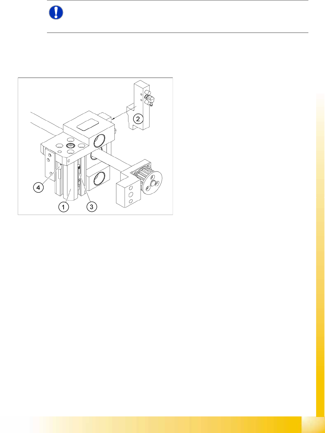
11-13: Overview of the proximity switches on the adjustment unit for width
adjustment
Legend
1. Pneumatic cylinder
2. Solenoid valve
3. Proximity switch for pneumatic cylinder (for
"locking pin up" recognition)
4. Proximity switch for adjustment unit(for
conveyor side recognition)
The proximity switch (3) serves as a signal for
controlling the pneumatic valve of the
adjustment unit. Once the switching point
"conveyor side present" has been reached,
the conveyor side is connected via the
pneumatic valve.
Modular Conveyor
Conveyor Settings Setting the Laser Light Barrier for the Stopper Position
Student Guide (FSE) SIPLACE X Series and X4I
Modular Conveyor Edition 01/2009 EN
456
11.3.3.2 Setting the Pneumatic Cylinder Proximity Switch on the Adjustment Unit
X Set any conveyor width. The adjustment units are positioned directly under the conveyor side.
X Start the I/O menu.
X Activate the pneumatic cylinder.
X Set the proximity switch on the pneumatic cylinder so that the LED (H35/H37 for TSP 301) (H64/65
for TSP 201) shines when connected.
11.3.4 Setting the Laser Light Barrier for the Stopper Position
Tools
[00369205-xx] Setting gauge for laser light barrier
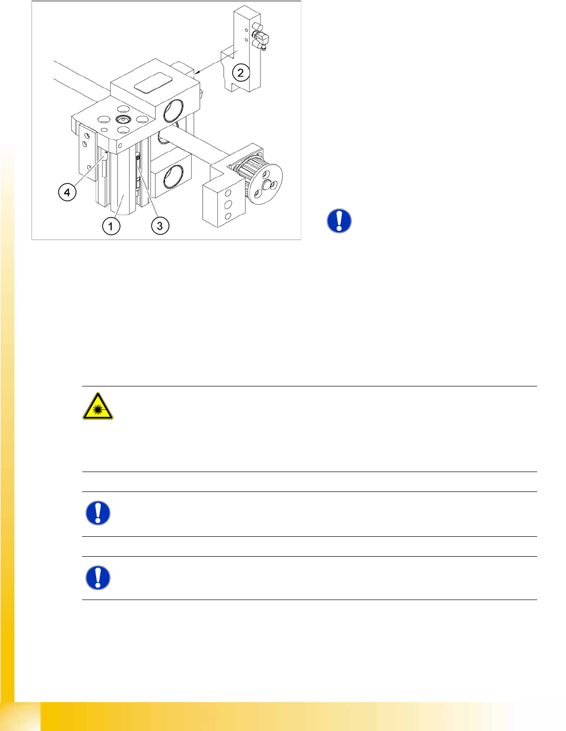
11-14: Overview of the proximity switches on the adjustment unit for width
adjustment
Legend
1. Pneumatic cylinder
2. Solenoid valve
3. Proximity switch for pneumatic cylinder (for
"locking pin up" recognition)
4. Proximity switch for adjustment unit(for
conveyor side recognition)
The proximity switch (3) on the adjustment unit
cylinder should operate when the adjustment
unit pin is pushed out by the pneumatic
cylinder and therefore connected to the
conveyor rail. This signal enables the width
adjustment motor.
NOTE:
The proximity switch on the pneumatic
cylinder is set when engaged.
The proximity switch is off when the
cylinder is extended into free space.
DANGER: Laser class 2
The laser light barrier transmitter emits class 2 laser beams. You do not need to take additional
protective measures!
X However, you should never look into the laser beam.
X Do the adjustment of the LASER Diode Beam direction only from the rear side of the LASER
(left machine side).
NOTE:
The laser beam deflection has greatest effect at the maximum conveyor width, it should always
be calibrated at the maximum conveyor width.
NOTE:
After setting the laser light barrier you must check or re-teach the PCB reference corner!