00196044-05 - sg x und x4i fse_en.pdf - 第466页
Modular Conveyor Conveyor Settings Conveyor Control TSP 301 S tudent Guide (FSE) SI PL ACE X Series and X4I Modular Conveyor Edition 01/2009 EN 466 1 1.3.10.3 LED Display on Conveyor Control TSP 301 1 1.3.10.4 Assignment…
Modular Conveyor
Conveyor Control TSP 301 Conveyor Settings
Student Guide (FSE) SIPLACE X Series and X4I
Edition 01/2009 EN Modular Conveyor
465
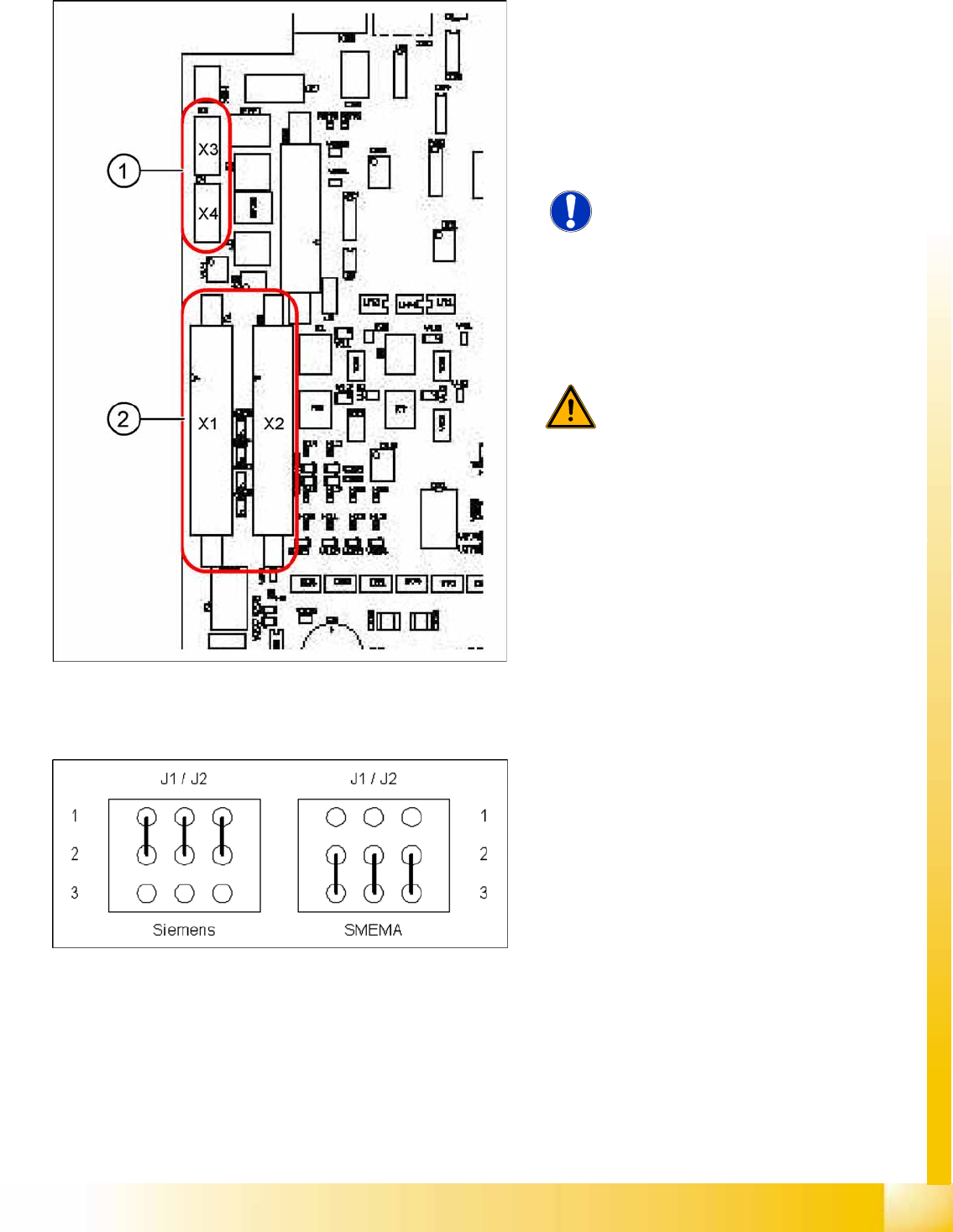
11.3.10.2 Conveyor Control TSP 301 with Siemens Interface
11-25: TSP 301 SMEMA --> Siemens
Legend
1. 10-pin plug for SMEMA interface
X3: upstream station
X4: downstream station
2. Connection for Siemens interface
X1: upstream station
X2: downstream station
NOTE: Standard / option
The SMEMA interface is the standard
and the Siemens interface optional for
all X machines.
The Siemens interface is the standard
and the SMEMA interface optional for
all D machines. An adapter is required
for the SMEMA interface when used on
D1/2/4 machines.
WARNING: Irreparable damage to the
TSP board!
The 10 pin Locking clip plug of SMEMA
connections must be disconnected
from the TSP 301!
Application: no modification.
Following modification are necessary for using the
Siemens interface:
X JumperJ1 / J2: need to be moved (see
following diagram).
X Disconnect the connector X3 and X4 on the
TSP 301!
X Connect the Siemens interface cable on the
connector X1 and X2.
11-26: Jumper J1 and J2 (Siemens/SMEMA)
Modular Conveyor
Conveyor Settings Conveyor Control TSP 301
Student Guide (FSE) SIPLACE X Series and X4I
Modular Conveyor Edition 01/2009 EN
466
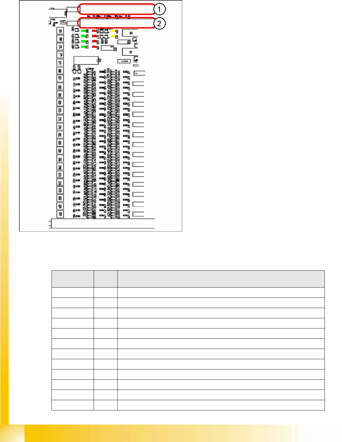
11.3.10.3 LED Display on Conveyor Control TSP 301
11.3.10.4 Assignment Table: LEDs on the TSP 301 Conveyor Control
11-27: Conveyor Control TSP 301
Legend
1. Connector Siemens PCB handling interface
upstream station lane 1 with corresponding
LEDs PCB handling
2. Connector Siemens PCB handling interface
upstream station lane 1 with corresponding
LEDs PCB handling
The connector "Siemens PCB handling interface
for the upstream station of lane 2 with
corresponding LEDs for PCB handling" and the
connector "PCB handling interface for the
downstream station of lane 2 with corresponding
LEDs for PCB handling" are located on the
extension board (similar layout).
Anzeige
/Display
I / O LED assignment
H1 / F1-F5 Fuse F1-F5, Power supply 40 V
H2 / F6 Fuse F6 Power supply 24V
H4(ao) Initializing / control error
H5(ao) CAN bus 1, active
H6(ao) Flashing: Program running
H7(ao) CAN bus 2, active (optional)
H9 Out Interference loop
H14 IN Siemens interface for upstream station
H15 IN Siemens interface for downstream station
H20 IN Lifting table, placement area 1: Fork light barrier A
H21 IN Lifting table, placement area 1: Fork light barrier B
H22 IN Lifting table, placement area 2: Fork light barrier A

Modular Conveyor
Conveyor Control TSP 301 Conveyor Settings
Student Guide (FSE) SIPLACE X Series and X4I
Edition 01/2009 EN Modular Conveyor
467
H23 IN Lifting table, placement area 2: Fork light barrier B
H24 IN Laser light barrier, placement area 1: Receiver
H25 IN Laser light barrier, placement area 2: Receiver
H26 IN Not in use
H27 IN Not in use
H28 IN Not in use
H29 IN Not in use
H30 IN Lifting table, placement area 1: Cylinder switch -
H31 IN Lifting table, placement area 2: Cylinder switch -
H32 IN Right side part: Limit switch
H33 IN Left side part: Limit switch
H34 IN Width adjustment Limit switch, Limit switch, right-hand side
H35 IN Not in use
H36(ao) IN Width adjusting unit 1 : Cylinder switch -
H37(ao) IN Width adjustment unit 2 : Cylinder switch -
H38(ao) IN Width adjusting unit 1 : Sensor side part
H39(ao) IN Width adjustment unit 2 : Sensor side part
H40(ao) IN Width adjustment spindle: Limit switch, right-hand side
H41(ao) IN Width adjustment spindle: Limit switch, left-hand side
H42(ao) IN Not in use
H43(ao) IN Not in use
H44 IN PCB sensor for input conveyor
H45 IN PCB sensor for placement area 1
H46 IN PCB sensor for intermediate conveyor
H47 IN PCB sensor for placement area 2
H48 IN PCB sensor for output conveyor
H49 IN Not in use
H50 IN Not in use
H51 IN Not in use
H52 IN Light scanner "Fluxing", input conveyor
H53 IN Light scanner "Fluxing", placement area 1
H54 IN Light scanner "Fluxing", intermediate conveyor
H55 IN Light scanner "Fluxing", placement area 2
H56 IN Light scanner "Fluxing", output conveyor
H57 IN Not in use
H58 IN Option plug, placement area 1: Input 1
H59 IN Option plug, placement area 1: Input 2
H60 IN Option plug, placement area 1: Input 3
H61 IN Option plug, placement area 1: Input 4
H62 IN Option plug, placement area 1: Input 5
H63 IN Option plug, placement area 1: Input 6
Anzeige
/Display
I / O LED assignment