00196044-05 - sg x und x4i fse_en.pdf - 第478页
Calibration Calibration of Entire Machine Calibration in General / Twin Head S tudent Guide (FSE) SI PL ACE X Series and X4I Calibration Edition 01/2009 EN 482 12.3.2 Calibration in General / T win Head 12-3: General seq…
Calibration
Calibration in General / C&P and CPP Calibration of Entire Machine
Student Guide (FSE) SIPLACE X Series and X4I
Edition 01/2009 EN Calibration
481
Requirements for calibration
X Switch the machine on.
X Switch the user level to at least
Service (customer)
.
X Perform an overall reference run.
X Use the nozzle changer to help you configure the heads to be calibrated with the calibration nozzles.
X Place the calibration tools into the calibration tool pockets.
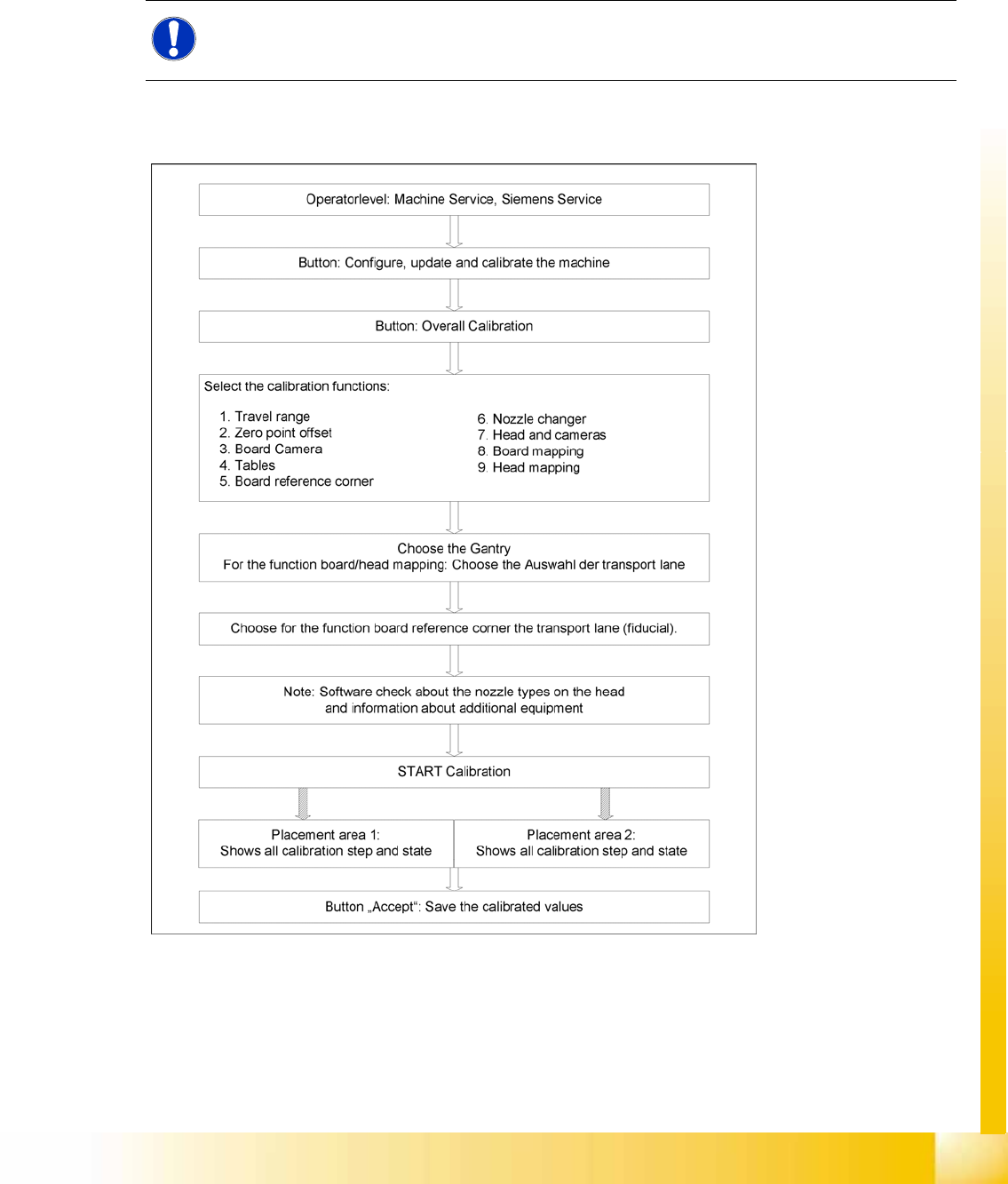
12.3.1 Calibration in General / C&P and CPP
12-2: General sequence to calibrate the machine
NOTE:
Before you place the calibration tool, make sure that it is clean. Also, be sure that you insert it
into the "calibration pocket" with its print of the fiducial structure on the bottom.
Calibration
Calibration of Entire Machine Calibration in General / Twin Head
Student Guide (FSE) SIPLACE X Series and X4I
Calibration Edition 01/2009 EN
482
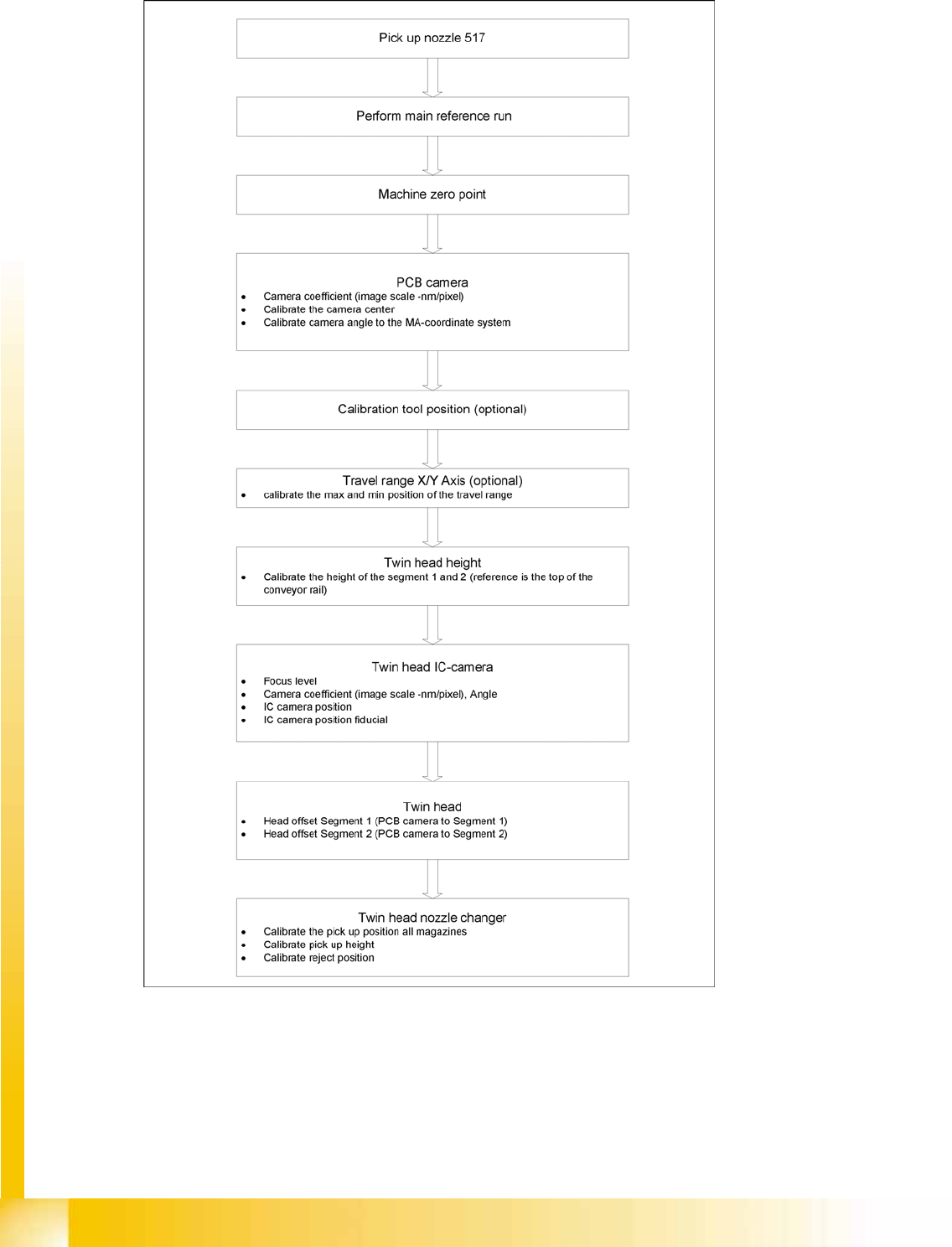
12.3.2 Calibration in General / Twin Head
12-3: General sequence to calibrate the machine
Calibration
Calibrating the Whole Machine with C&P Head as Example Calibration of Entire Machine
Student Guide (FSE) SIPLACE X Series and X4I
Edition 01/2009 EN Calibration
483
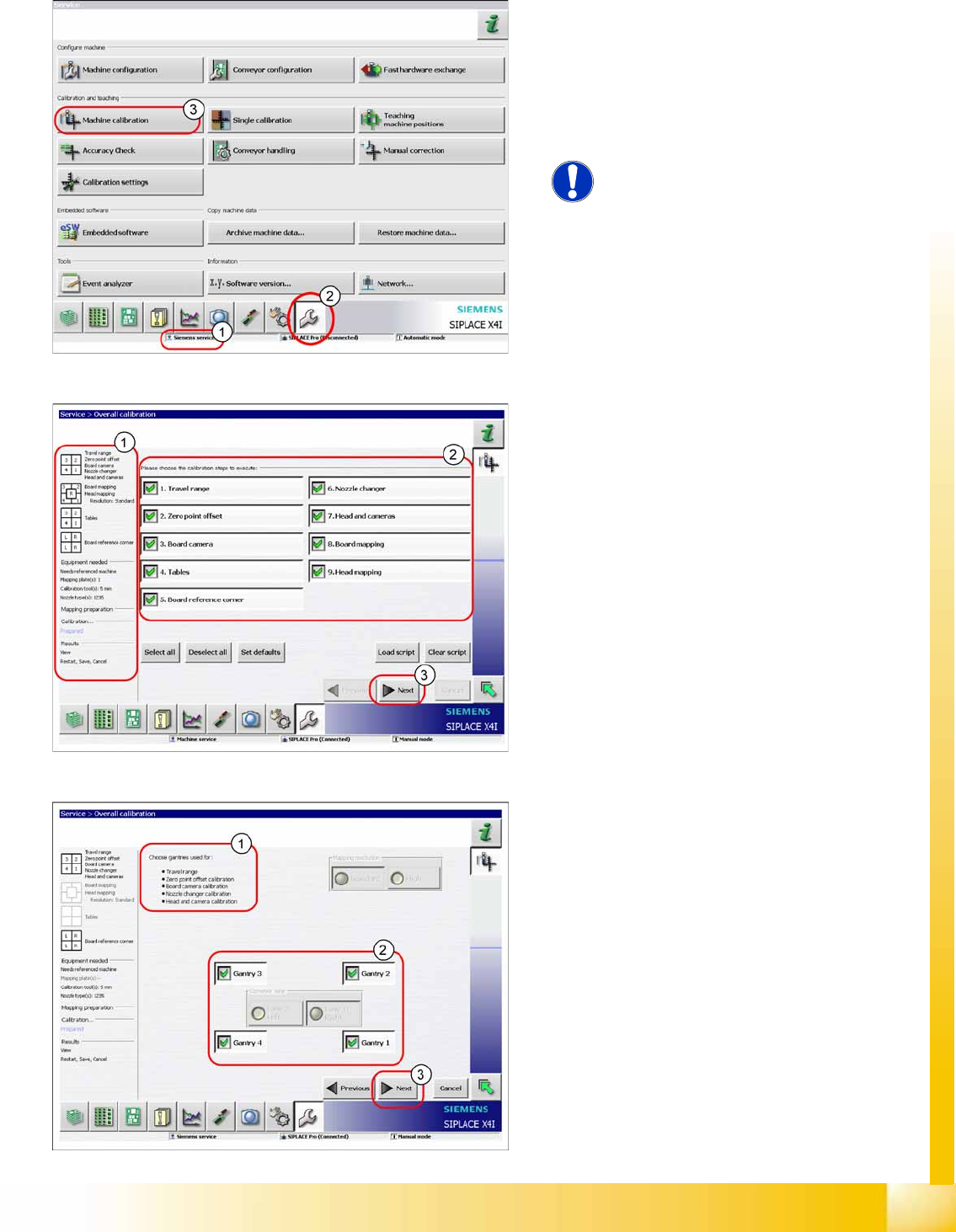
12.3.3 Calibrating the Whole Machine with C&P Head as Example
The entire machine calibration function can be
performed with user level (1)
Service (customer)
or
Siemens Service
.
X Switch over to the service menu (2).
X Click on
Overall calibration
(3) button, to start
the wizard.
NOTE:
Calibration of the conveyor sides and
widths needs to be performed with the
menu
Single calibration
.
In area (1) you will see information about the
selected calibration steps, the required equipment
and the results. Area (2) allows you to select or
deselect individual calibration steps.
X Select the required calibration steps.
X Click on
Next
(3).
Area (1) shows the selected calibration steps.
X In area (2), select the gantries to be calibrated.
When performing PCB or head mapping, you
can also select the conveyor lane.
X Click on
Next
(3).