00196044-05 - sg x und x4i fse_en.pdf - 第479页
Calibration Calibrating the Whole Machine with C&P Head as Example Calibration of Entire Machine S tudent Guide (FSE) SIPL ACE X Series and X4I Edition 01/2009 EN Calibration 483 12.3.3 Calibrating the Whole Mach ine…
Calibration
Calibration of Entire Machine Calibration in General / Twin Head
Student Guide (FSE) SIPLACE X Series and X4I
Calibration Edition 01/2009 EN
482
12.3.2 Calibration in General / Twin Head
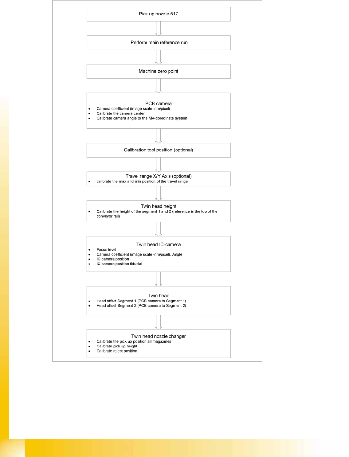
12-3: General sequence to calibrate the machine
Calibration
Calibrating the Whole Machine with C&P Head as Example Calibration of Entire Machine
Student Guide (FSE) SIPLACE X Series and X4I
Edition 01/2009 EN Calibration
483
12.3.3 Calibrating the Whole Machine with C&P Head as Example
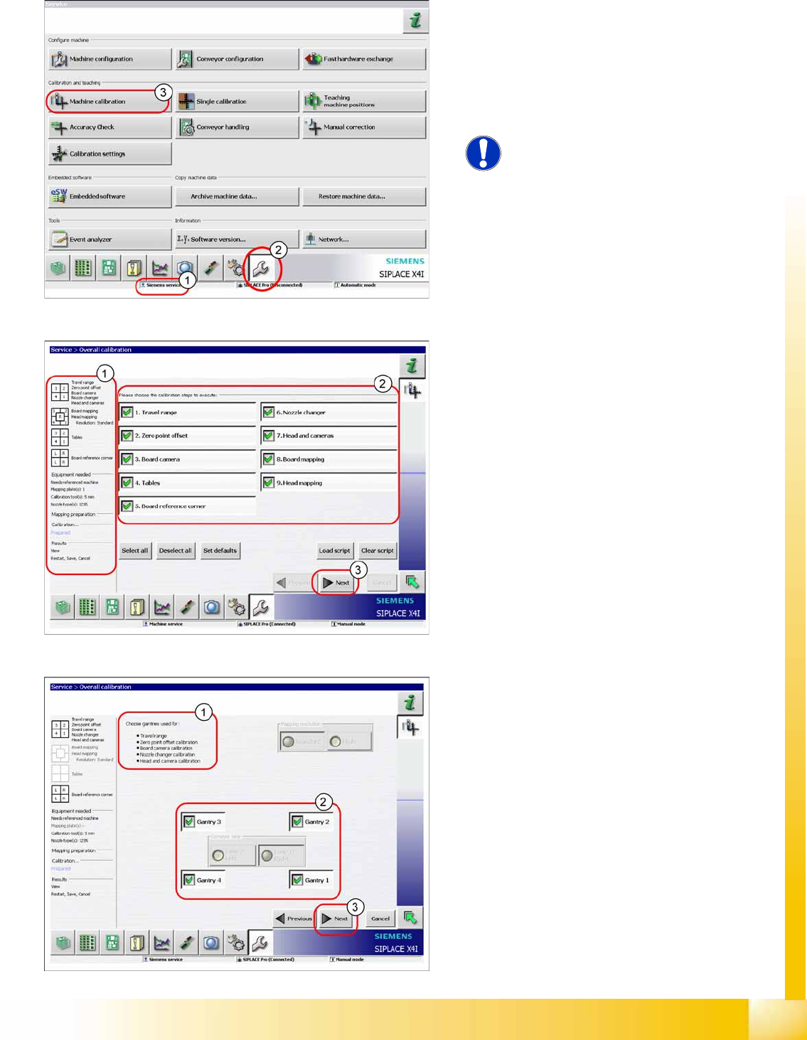
The entire machine calibration function can be
performed with user level (1)
Service (customer)
or
Siemens Service
.
X Switch over to the service menu (2).
X Click on
Overall calibration
(3) button, to start
the wizard.
NOTE:
Calibration of the conveyor sides and
widths needs to be performed with the
menu
Single calibration
.
In area (1) you will see information about the
selected calibration steps, the required equipment
and the results. Area (2) allows you to select or
deselect individual calibration steps.
X Select the required calibration steps.
X Click on
Next
(3).
Area (1) shows the selected calibration steps.
X In area (2), select the gantries to be calibrated.
When performing PCB or head mapping, you
can also select the conveyor lane.
X Click on
Next
(3).
Calibration
Calibration of Entire Machine Calibrating the Whole Machine with C&P Head as Example
Student Guide (FSE) SIPLACE X Series and X4I
Calibration Edition 01/2009 EN
484
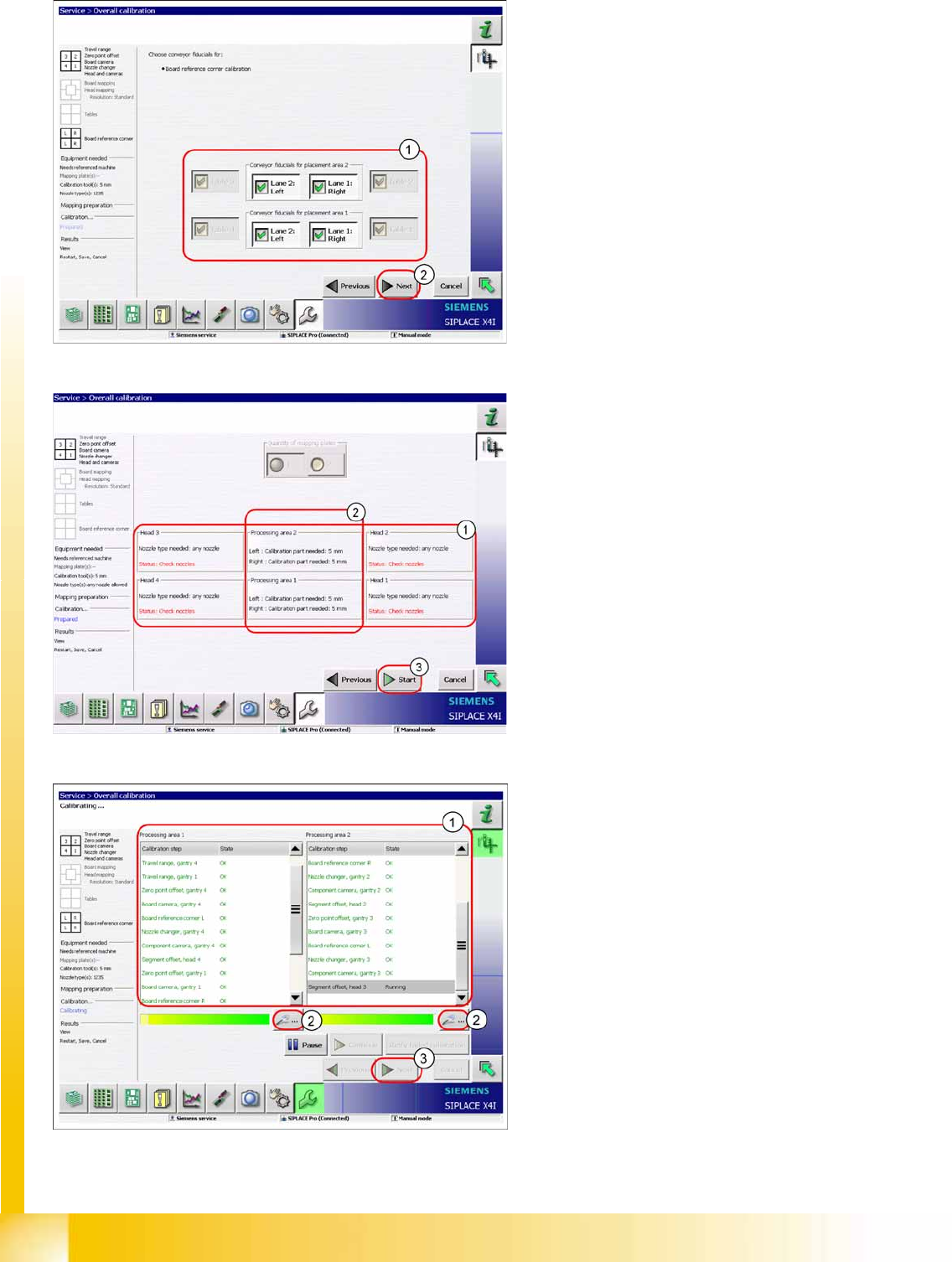
X Select the tables and PCB reference corners
(1) to be calibrated.
X Click on the
Start
(2).
X Check whether the heads are fitted with the
correct nozzles (1). If not, this can be corrected
now.
X Please note that each calibration tool pocket
must be fitted with a calibration tool (2).
X Click on
Start
(3).
The calibration will begin and the following
image will be shown.
X Area (1) shows the status of the calibration
steps for the relevant processing area. For
further details, select the zoom button (2) (see
next diagram).
X Click on
Next
(3) button to save the calibration
values.