00196044-05 - sg x und x4i fse_en.pdf - 第481页
Calibration Single calibration Calibration of Entire Machine S tudent Guide (FSE) SIPL ACE X Series and X4I Edition 01/2009 EN Calibration 485 12.3.4 Single calibration 12.3.4.1 Calibrating the Conveyor Sides and Wid ths…
Calibration
Calibration of Entire Machine Calibrating the Whole Machine with C&P Head as Example
Student Guide (FSE) SIPLACE X Series and X4I
Calibration Edition 01/2009 EN
484
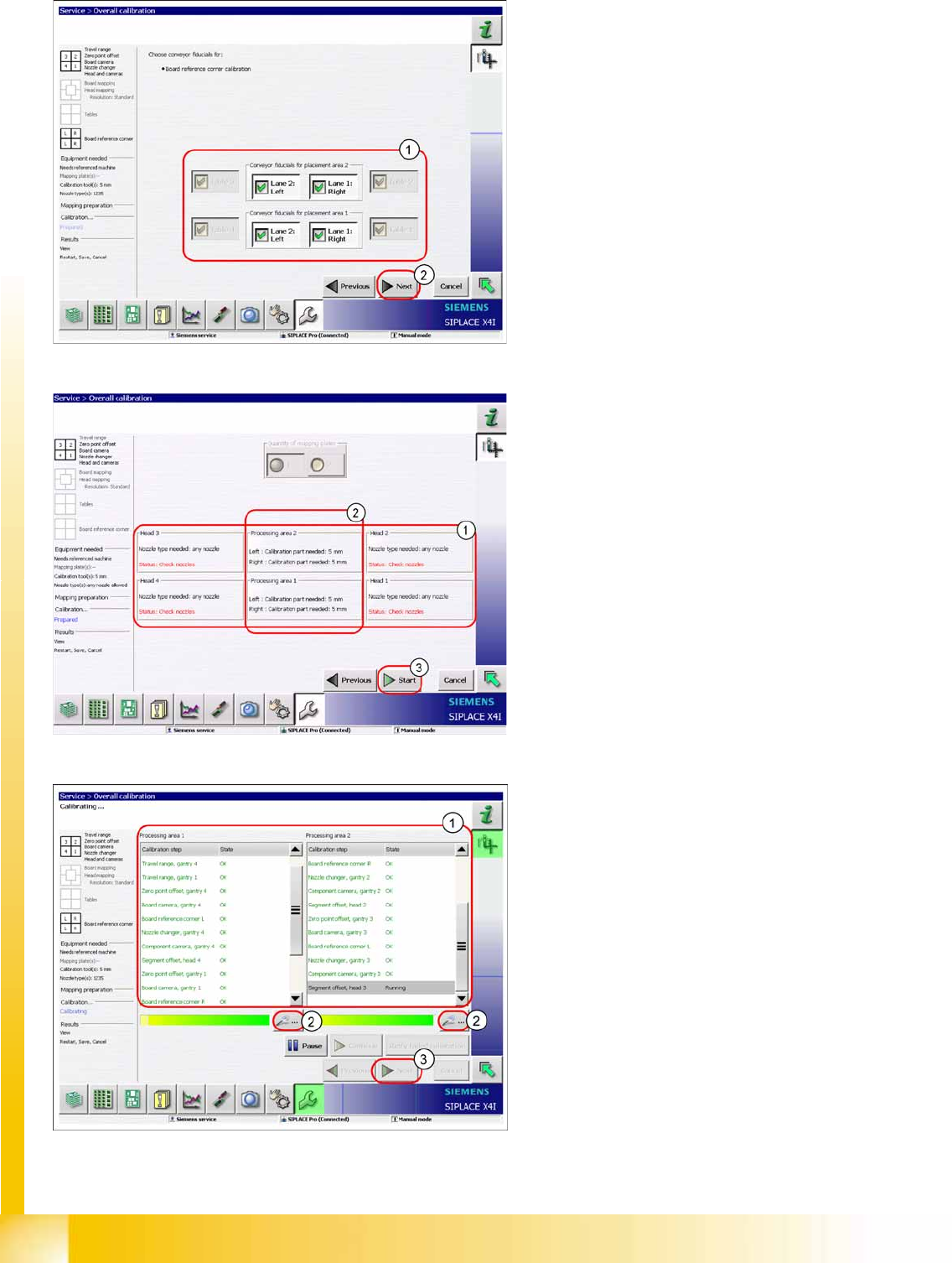
X Select the tables and PCB reference corners
(1) to be calibrated.
X Click on the
Start
(2).
X Check whether the heads are fitted with the
correct nozzles (1). If not, this can be corrected
now.
X Please note that each calibration tool pocket
must be fitted with a calibration tool (2).
X Click on
Start
(3).
The calibration will begin and the following
image will be shown.
X Area (1) shows the status of the calibration
steps for the relevant processing area. For
further details, select the zoom button (2) (see
next diagram).
X Click on
Next
(3) button to save the calibration
values.
Calibration
Single calibration Calibration of Entire Machine
Student Guide (FSE) SIPLACE X Series and X4I
Edition 01/2009 EN Calibration
485
12.3.4 Single calibration
12.3.4.1 Calibrating the Conveyor Sides and Widths
See also:
J
12.4.11 Conveyor Width Calibration [
J
492]
J
12.4.10 Conveyor Sides [
J
492]
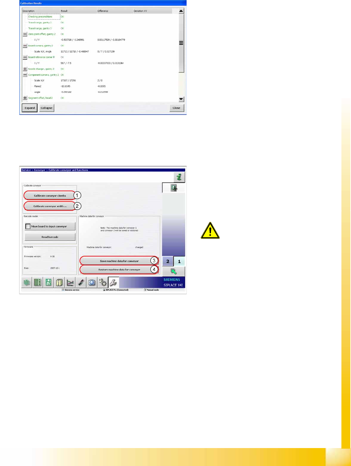
Calibration results in detail
Legend
1. Calibrate the conveyor sides.
2. Conveyor Width Calibration
3. Store machine data for the conveyor
4. Restore machine data for the conveyor
ATTENTION:
Calibration of the conveyor sides and
widths is not included in the function
Overall calibration
.
X Use the function
Single calibration
and click on the
Conveyor
.
The machine data for the conveyor are
automatically stored on the TSP301. The backup
file for restoring data is stored on the station
computer.
Calibration
General Explanation of Calibration Steps Travel Range (Optional)
Student Guide (FSE) SIPLACE X Series and X4I
Calibration Edition 01/2009 EN
486
12.4 General Explanation of Calibration Steps
12.4.1 Travel Range (Optional)
See also:
J
6 Gantry [
J
209]
12.4.2 Zero Point Offset
The machine zero point (measurement point for each gantry) serves as the reference point for the X and
Y axes to the machine coordinate system. This means that both axes know exactly where they are in the
machine.
This machine point (fiducial) is approached with the help of the PCB camera and is measured in the X
and Y direction. The resulting offset is added to the fixed zero point correction value for the X and Y axis.
See also:
J
12.2.2 Calibration Position – Machine Zero Points [
J
479]
12.4.3 PCB Camera
Determining the calibration factors, relation of camera pixel size to resolution of machine
measurement system (X, Y).
The camera center point is determined in the X and Y directions.
Determining the rotation angle of the CCD sensor in the PCB camera.
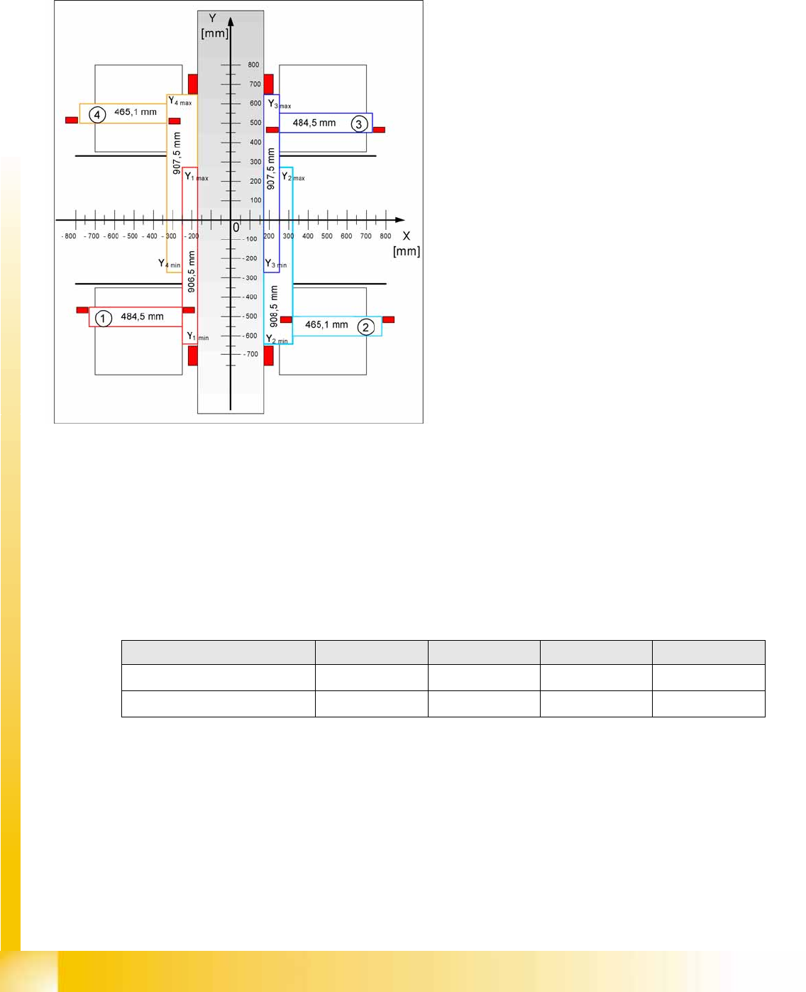
The evaluation of the maximum and minimum
travel range for machines with A364 is
performed via the hardware bumpers. These
values are required for monitoring the travel
range, the speed and the gantry.
The X axis moves to the left and right bumper
and measures their positions with a safety
distance of 2.0 mm. A safety distance of
0.5 mm is also taken into account by the
software.
The Y axis moves to its minimum position
(gantry 1/2) or maximum position (gantry 3/4).
Machine zero point Gantry 1 Gantry 2 Gantry 3 Gantry 4
X
nominal
-368.7 mm 368.7 mm 368.7 mm -368.7 mm
Y
nominal
-298.0 mm -298.0 mm 298.0 mm 298.0 mm