00196044-05 - sg x und x4i fse_en.pdf - 第483页
Calibration Tables General Explanation of Calibration Steps S tudent Guide (FSE) SIPL ACE X Series and X4I Edition 01/2009 EN Calibration 487 12.4.4 T ables During machine calibration, each gantry moves to the fiducials …
Calibration
General Explanation of Calibration Steps Travel Range (Optional)
Student Guide (FSE) SIPLACE X Series and X4I
Calibration Edition 01/2009 EN
486
12.4 General Explanation of Calibration Steps
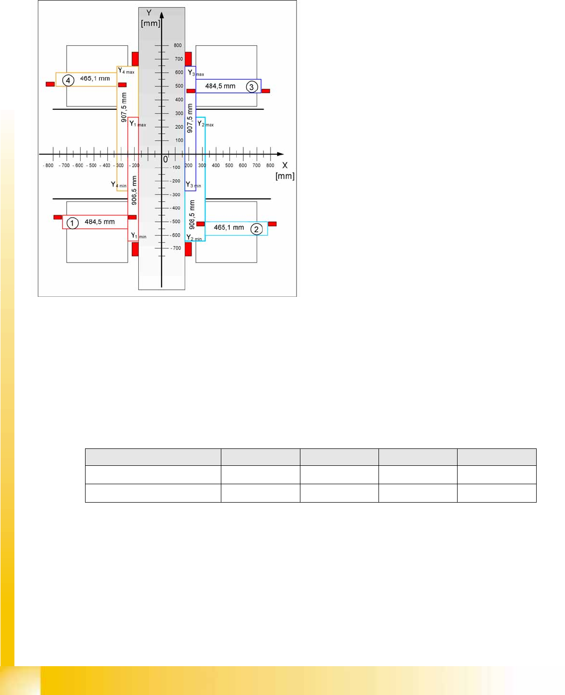
12.4.1 Travel Range (Optional)
See also:
J
6 Gantry [
J
209]
12.4.2 Zero Point Offset
The machine zero point (measurement point for each gantry) serves as the reference point for the X and
Y axes to the machine coordinate system. This means that both axes know exactly where they are in the
machine.
This machine point (fiducial) is approached with the help of the PCB camera and is measured in the X
and Y direction. The resulting offset is added to the fixed zero point correction value for the X and Y axis.
See also:
J
12.2.2 Calibration Position – Machine Zero Points [
J
479]
12.4.3 PCB Camera
Determining the calibration factors, relation of camera pixel size to resolution of machine
measurement system (X, Y).
The camera center point is determined in the X and Y directions.
Determining the rotation angle of the CCD sensor in the PCB camera.
The evaluation of the maximum and minimum
travel range for machines with A364 is
performed via the hardware bumpers. These
values are required for monitoring the travel
range, the speed and the gantry.
The X axis moves to the left and right bumper
and measures their positions with a safety
distance of 2.0 mm. A safety distance of
0.5 mm is also taken into account by the
software.
The Y axis moves to its minimum position
(gantry 1/2) or maximum position (gantry 3/4).
Machine zero point Gantry 1 Gantry 2 Gantry 3 Gantry 4
X
nominal
-368.7 mm 368.7 mm 368.7 mm -368.7 mm
Y
nominal
-298.0 mm -298.0 mm 298.0 mm 298.0 mm

Calibration
Tables General Explanation of Calibration Steps
Student Guide (FSE) SIPLACE X Series and X4I
Edition 01/2009 EN Calibration
487
12.4.4 Tables
During machine calibration, each gantry moves to the fiducials for the corresponding table. Gantry 1
approaches the fiducials for table 1 at location 1 and so on.
So-called dummy feeders with an additional table fiducial are fitted at gantries 2 and 4, as the rotated
gantries limit the travel range at these locations.
The fiducials are used to calculate the X, Y and angle positions of the table in the machine.
Information about the position of the fiducials can be found in the section Calibration Position.
12.4.5 PCB Reference Corner
The PCB reference corner is determined via a fiducial which is integrated into each conveyor side. An
offset for the real PCB reference corner is stored in the software. The calibration data plus the offset
gives the PCB reference corner.
This position tells the software where the board is in the machine and forms a reference point to the
board coordinate system.
Information about the position of the fiducials can be found in the section Calibration Position.
12.4.6 Nozzle Changer and Nozzle Station
Each nozzle magazine and nozzle station has two fiducials.
When calibrating the NC and the nozzle station, the system first approaches the two fiducials for the
nozzle station and measures the height of the nozzle station with the help of the Z axis and a nozzle of
your choice.
After this, each magazine is approached and its two fiducials and Z-height are ensured. This is
performed in one calibration step for each magazine.
You do not need a special nozzle for calibrating the Z-height and the component level in the magazine
is of no relevance. The Z-height can be measured with a nozzle of your choice, on the top edge of the
magazine.
The Z-height is then calculated from the nozzle length, Z-position at top edge of magazine and a fixed
value for the nozzle garage.
Information about the position of the fiducials can be found in the section Calibration Position.
Calibration
General Explanation of Calibration Steps Heads and Cameras
Student Guide (FSE) SIPLACE X Series and X4I
Calibration Edition 01/2009 EN
488
12.4.7 Heads and Cameras
When calibrating the heads and cameras, the component camera is measured first, followed by the
segment offsets at the top and bottom. The head offset and the top/bottom segment offsets are
measured in one calibration step.
Component Camera
Determining the calibration factors, relation of camera pixel size to resolution of machine
measurement system (X, Y).
The camera center is determined.
The mounting angle of the CCD sensor in the component camera, compared to the turning level of
the placement star, is measured.
Head offset
The head offset is the distance between the PCB camera and the nozzle (segment 1). The target value
is a fixed value (X = 0 and Y = -105 mm), to which an offset value (from head calibration) is added.
Segment offset
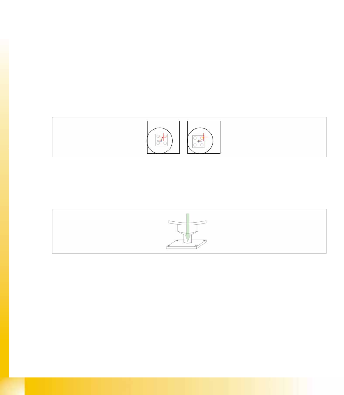
The segment offsets top and bottom are determined in one calibration step for each segment.
For the segment offset top, the calibration tool is rotated in 0°, 90°, 180° and 270° steps inside the
component camera. The rotating center point of the nozzle tip, in relation to the component camera
center, is then determined in the X and Y directions. (see diagram)
12-4: Segment offset top
For the segment offset bottom the calibration tool is placed into the calibration tool pocket in 0°, 90°,
180° and 270° positions and is measured with the PCB camera. The rotating center point of the nozzle
tip - when the Z axis is extended - is then determined in relation to the PCB camera. In this case,
segment1 is taken as reference with a value of 0.
12-5: Segment offset bottom