00196044-05 - sg x und x4i fse_en.pdf - 第486页
Calibration General Explanation of Calibratio n Steps Heads and Cameras S tudent Guide (FSE) SI PL ACE X Series and X4I Calibration Edition 01/2009 EN 490 12.4.7.2 IC camera: After measuring the he ad height of Twin he…
Calibration
Heads and Cameras General Explanation of Calibration Steps
Student Guide (FSE) SIPLACE X Series and X4I
Edition 01/2009 EN Calibration
489
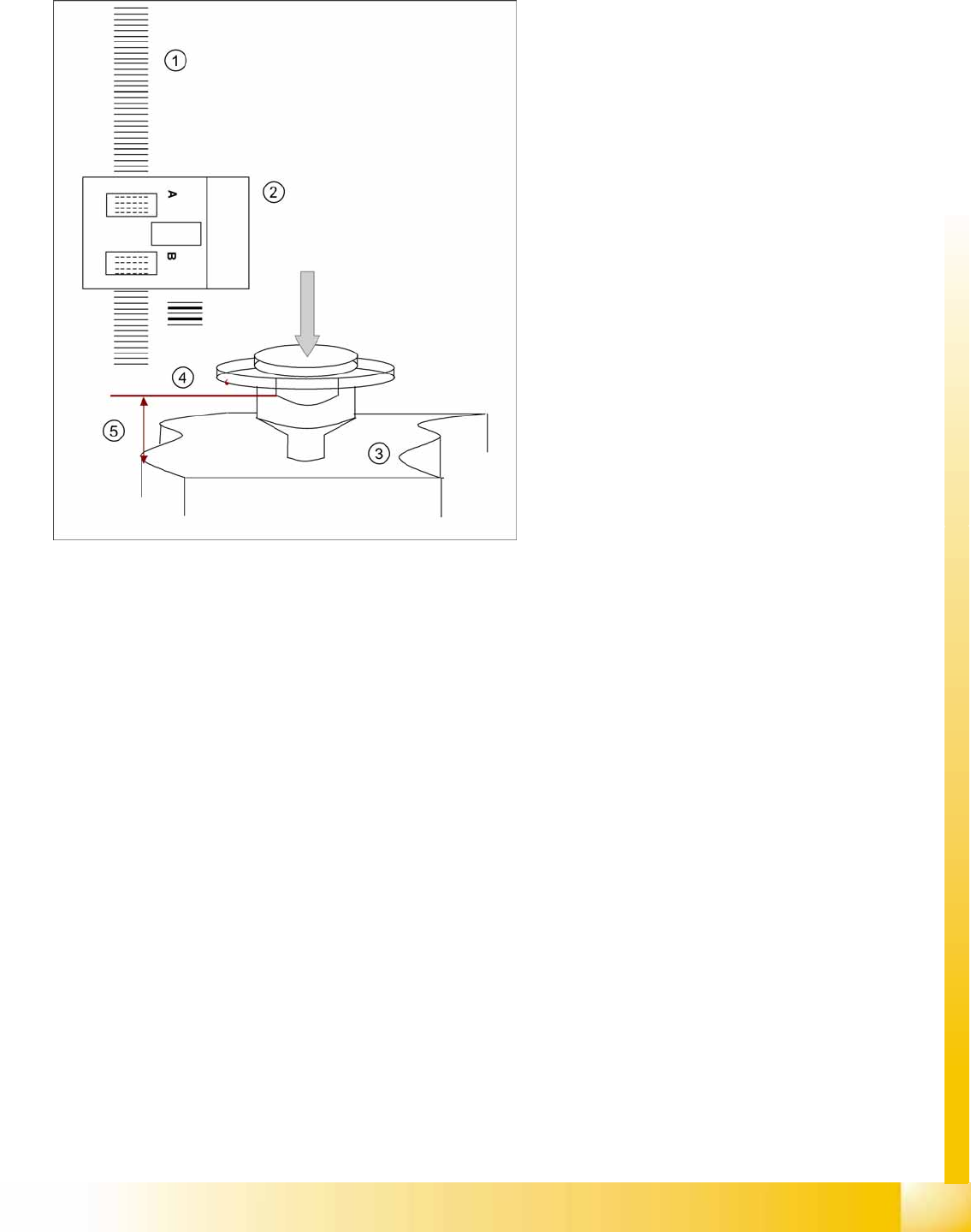
12.4.7.1 Twin head height:
Calibrate Head height mean to determine Z Zero point correction.
Procedure:
move to zero pulseset the position counter to 0
move with 517 nozzle to the conveyor side
subtract ‘Kopfhöhe’ head height from Ideal.ma (65500)
subtract theoretical nozzle length
is zero point correction Z pos.act. -nozzle length -head height = 0-corr.
12-6: Twin head height
Legend
1. Z axis incremental encoder
2. Incremental encoder fixed
3. Top edge of the conveyor side
4. Head height
5. Nozzle length

Calibration
General Explanation of Calibration Steps Heads and Cameras
Student Guide (FSE) SIPLACE X Series and X4I
Calibration Edition 01/2009 EN
490
12.4.7.2 IC camera:
After measuring the head height of Twin head (Z axis zero point correction) the Twin -IC camera is
calibrated.
The first measurement is the focus level for the stationary camera. That means, the Twin head move
with the Z axis of the cover from the stationary camera. (This height is the centering height for bottom
side of components.)
The Pixel size in µm of the camera is determined next. Saved as:
/XU_Pixel / YU_Pixel/ of camera 11(in 79000 nm).
The camera center of the Twin- IC-camera refer to the zero point of the machine (X / Y counter zero
position).
These coordinates are entered in the cameras.xml file, in the camera data block of the relevant gantry:
Proximity values in nm
Resolution yuPixel=41750
xuPixel=41750
The calibration data for the IC camera are saved in the cameras.xml file.
Calibration IC camera position fiducial
12.4.7.3 FC camera: (Option)
After measuring the height of the Twin head, the FC camera is calibrated.
The first measurement is the focus level for the stationary camera. That means, the Twin head move
with the Z axis of the cover from the stationary camera. (This height is the centering height for bottom
side of components.)
The Pixel size in µm of the camera is determined next.
The following proximity value in nm is saved in the
cameras.xml
file, in the Camera data block for
the relevant gantry:
– yUPixel=16250
– xUPixel=16250
The camera center of the Twin- FC-camera refer to the zero point of the machine (X / Y counter zero
position).
Saved are all this data and coordinates in: KAM_DAT.MA in Data bloc camera 15: (Gantry 2)
camera_position_X / camera_position_Y/ camera_offset_Z/
Calibrate the IC camera position fiducial
12.4.7.4 Twin head segment offset bottom at segment 1 and 2:
That means the D axis, center of sleeve of the Twin (IC) -placement head refer to the camera center
of PCB-camera.
The coordinates saved in PIP_OFF.MA at Data bloc
/Nozzle offsets down head 2/
Nozzle offsets down segment 1(2) Offset_X /Offset_Y /
Calibration
PCB Mapping General Explanation of Calibration Steps
Student Guide (FSE) SIPLACE X Series and X4I
Edition 01/2009 EN Calibration
491
12.4.7.5 Nozzle Changer (C&P Head, Twin Head):
Each nozzle magazine has an fiducial which will recognize during the calibration procedure at first.
After that, the machine recognize the two fiducial of the holder from the magazine on the left and
right side.
optional, calibrate the pick up height from the nozzle changer.
optional, calibrate the reject position from the nozzle changer, necessary to reject nozzle which are
defekt.
12.4.7.6 Calibrate closed vacuum:
This function measure onto the fixed conveyor side with the nozzle 518 the closed vacuum values of the
vacuum system for the segment 1 and 2.
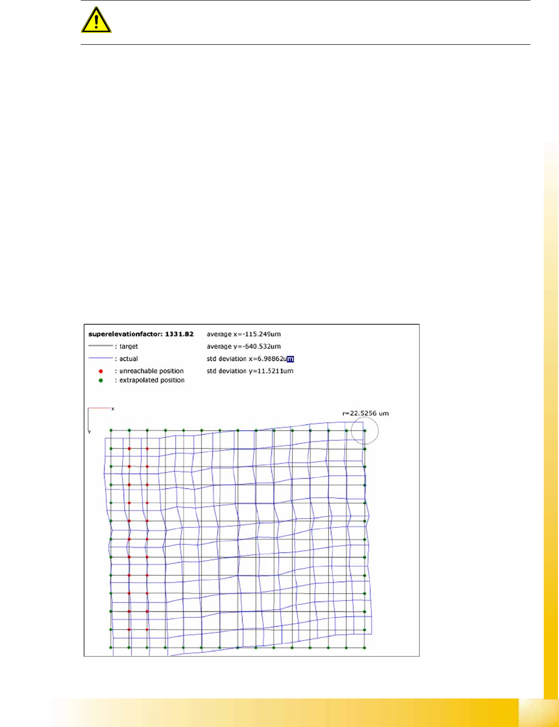
12.4.8 PCB Mapping
During PCB mapping, the right angular position of the X and Y axes to one another is measured with the
PCB camera for all gantries and conveyor lanes.
This also creates a reference to the position of the conveyor system to the gantry system. In this case,
the PCB camera is used to measure fiducial crosshairs on a high-precision glass plate.
This glass mapping plate has been calibrated with a measurement device and the measurement
protocol is taken into account for the mapping process.
12-7: Result of PCB mapping
The results are stored in an XML file for each gantry and conveyor lane.
ATTENTION:
Precondition for calibrate the nozzle changer is to check or determine the zero point correction
for the D - Axis Twinhead, the configuration of the nozzle changer and the fill level.