00196044-05 - sg x und x4i fse_en.pdf - 第509页
Calibration Configuring the Nozzle Changer Additional Functions S tudent Guide (FSE) SIPL ACE X Series and X4I Edition 01/2009 EN Calibration 513 Start the loca l ACT progra m Placement. Start the prescribed ACT program,…
Calibration
Additional Functions Autoconfiguration
Student Guide (FSE) SIPLACE X Series and X4I
Calibration Edition 01/2009 EN
512
12.6.6 Autoconfiguration
12.6.7 Nozzle Scanning
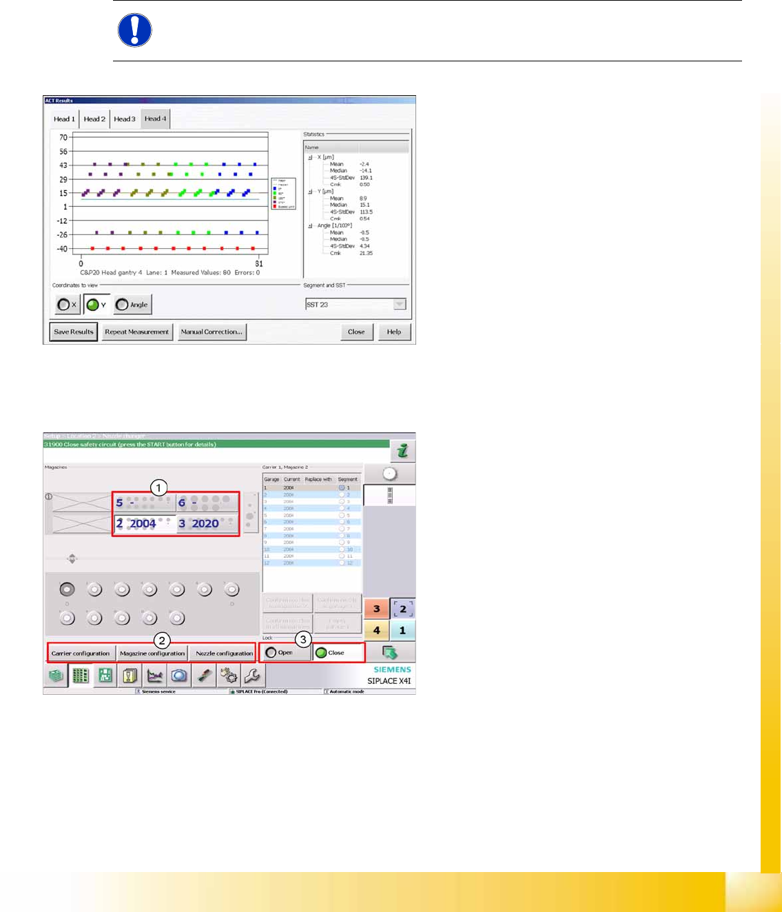
12.6.8 Accuracy Check Tool
The Accuracy Check Tool (ACT) can determine the placement accuracy of a machine.
A special board is placed and the components placed on it are then measured with the PCB camera.
ACT measurement:
Specify the ACT program in SIPLACE Pro. (The job must be locally available at the machine.)
Switch over to stand alone mode.The machine may not be in production mode. Press the STOP button.
Select the following operator level to enable the ACT
Service engineer
The automatic configuration of the machine is a
new function with the software 702. This function
locates the installed hardware components when
the machine is switched on.
The software installation only defines the machine
type X2, X3, X4 or X4I.
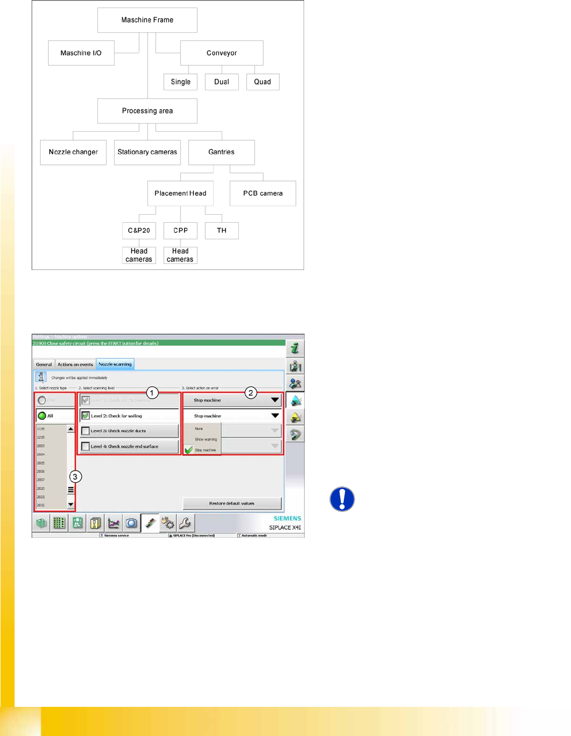
SW 702 provides an option for configuring nozzle
scanning for selected nozzle types (3) . There are
4 configuration levels (1).
Check nozzle position
Check for soiling
Check nozzle ducts
Check nozzle end surface
X Select an action if errors occur during nozzle
scanning (2).
NOTE:
Changes can only be made with the
operator level
Service Engineer
.
Calibration
Configuring the Nozzle Changer Additional Functions
Student Guide (FSE) SIPLACE X Series and X4I
Edition 01/2009 EN Calibration
513
Start the local ACT program
Placement.
Start the prescribed ACT program, now locally available at the station computer.
The results of the ACT measurement will be automatically shown as a graphic. (Detail measurements
will be stored in a text file.)
Save the results in a PDF file or apply the measured offsets to individual heads in the kinematic machine
model.
12.6.9 Configuring the Nozzle Changer
NOTE:
Measurement of the placed board can be repeated if necessary.
Results display
The individual measurements will be shown on a
graphic as points for X, Y and angle. The statistical
results will be shown in a tree structure, next to the
diagram.
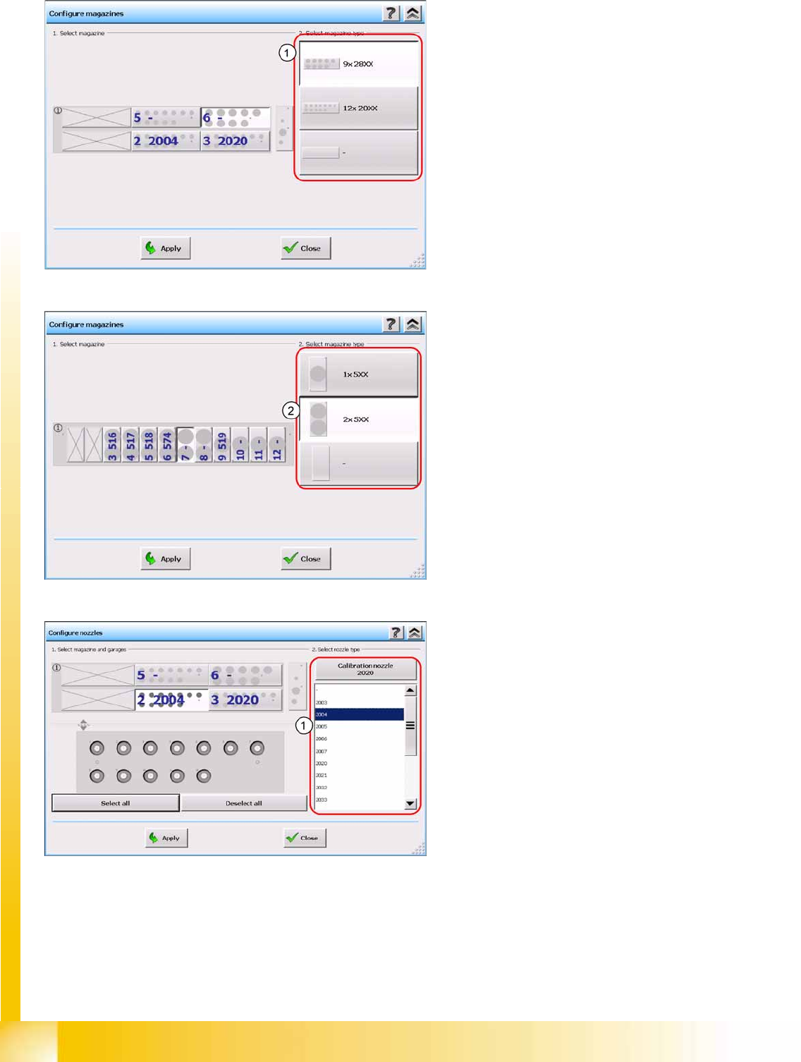
The integration of the Twin Head and the CPP
head requires various new settings: magazine
carrier configuration, magazine configuration and
nozzle configuration.
Calibration
Additional Functions Configuring the Nozzle Changer
Student Guide (FSE) SIPLACE X Series and X4I
Calibration Edition 01/2009 EN
514
Magazine configuration for CPP head
Magazines for 28xx nozzles
Magazines for 20xx nozzles
Magazine configuration for Twin Head
Magazine for a special nozzle
Magazine for two standard nozzles
Nozzle configuration
Example of CPP head