00196044-05 - sg x und x4i fse_en.pdf - 第522页
Head Modularity Head Modularity C&P20A to CPP Head Calibr ation S tudent Guide (FSE) SI PL ACE X Series and X4I Head Modularity Edition 01/2 009 EN 526 13.6 Head Modularity C&P20A to CPP Head Preparation: X Place…
Head Modularity
Calibration Head Modularity Twin Head to CPP/C&P
Student Guide (FSE) SIPLACE X Series and X4I
Edition 01/2009 EN Head Modularity
525
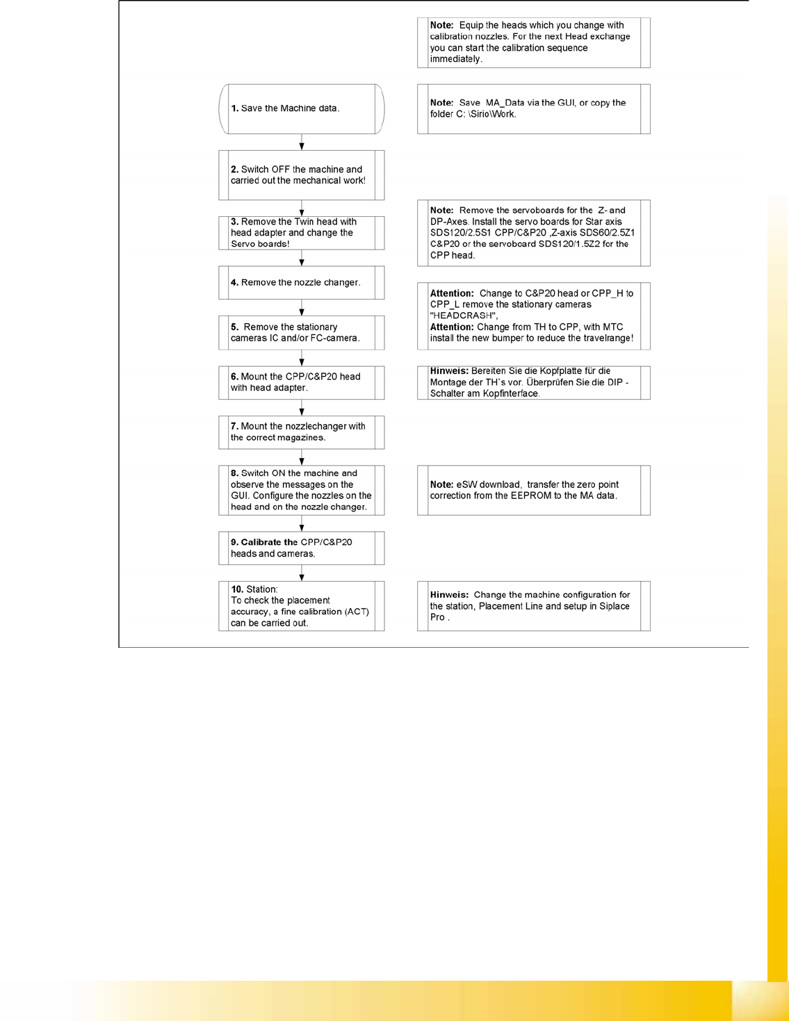
13.5 Head Modularity Twin Head to CPP/C&P
13-5: Procedure for head exchange TwinHead to CPP/C&P
Head Modularity
Head Modularity C&P20A to CPP Head Calibration
Student Guide (FSE) SIPLACE X Series and X4I
Head Modularity Edition 01/2009 EN
526
13.6 Head Modularity C&P20A to CPP Head
Preparation:
X Place the nozzles from all heads, even those which were not exchanged, in the nozzle changer.
X Back up the machine data with
Save machine data
.
X Switch off the machine.
X Dismantle the C&P20A placement head.
Protect the component sensor by fitting the red rubber hose onto the prisms and removing the
changeover table.
Remove the black compressed air hose from the distributor and from the head.
Loosen the flat ribbon cable from the head adapter but leave it on the head.
X Prepare the head plate as follows.
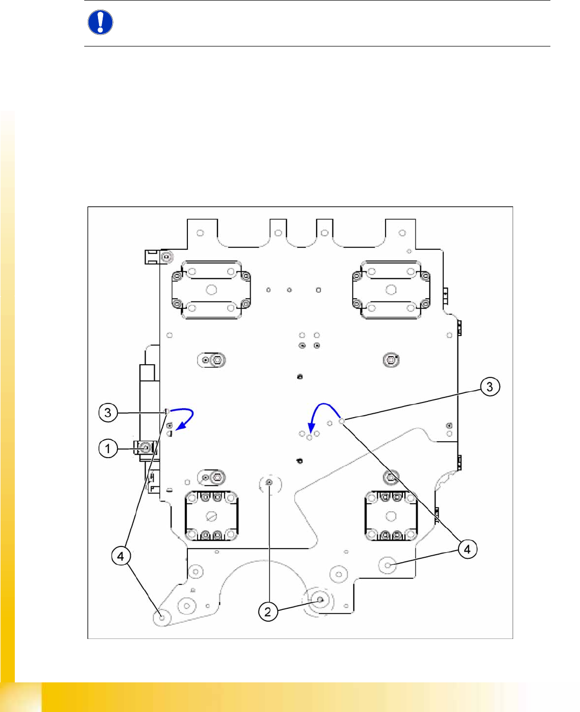
Preparing the X motor plate (head plate)
X Remove the cable holders (1).
NOTE:
After conversion, a new autoconfiguration file will be compiled when the machine is switched
back on.
Head Modularity
Calibration Head Modularity C&P20A to CPP Head
Student Guide (FSE) SIPLACE X Series and X4I
Edition 01/2009 EN Head Modularity
527
X Check the length of the centering pins (2) before fitting a CPP head.
This may only extend 4.0 mm (tolerance: -0.2 mm) from the head plate.
X Remove the grub screws (3) from the head plate.
X Seal the drilled holes on the C&P20A with these grub screws (3).
Seal the thread of the grub screws with Loctite 511.
X Fit the CPP head with 4 M4x18 and 2.7 Nm screws.
ATTENTION:
If the centering pins extend by more than 4.0 mm from the head plate, the incremental disk of
the star axis (glass) could be irreparably damaged during assembly of the CPP head!
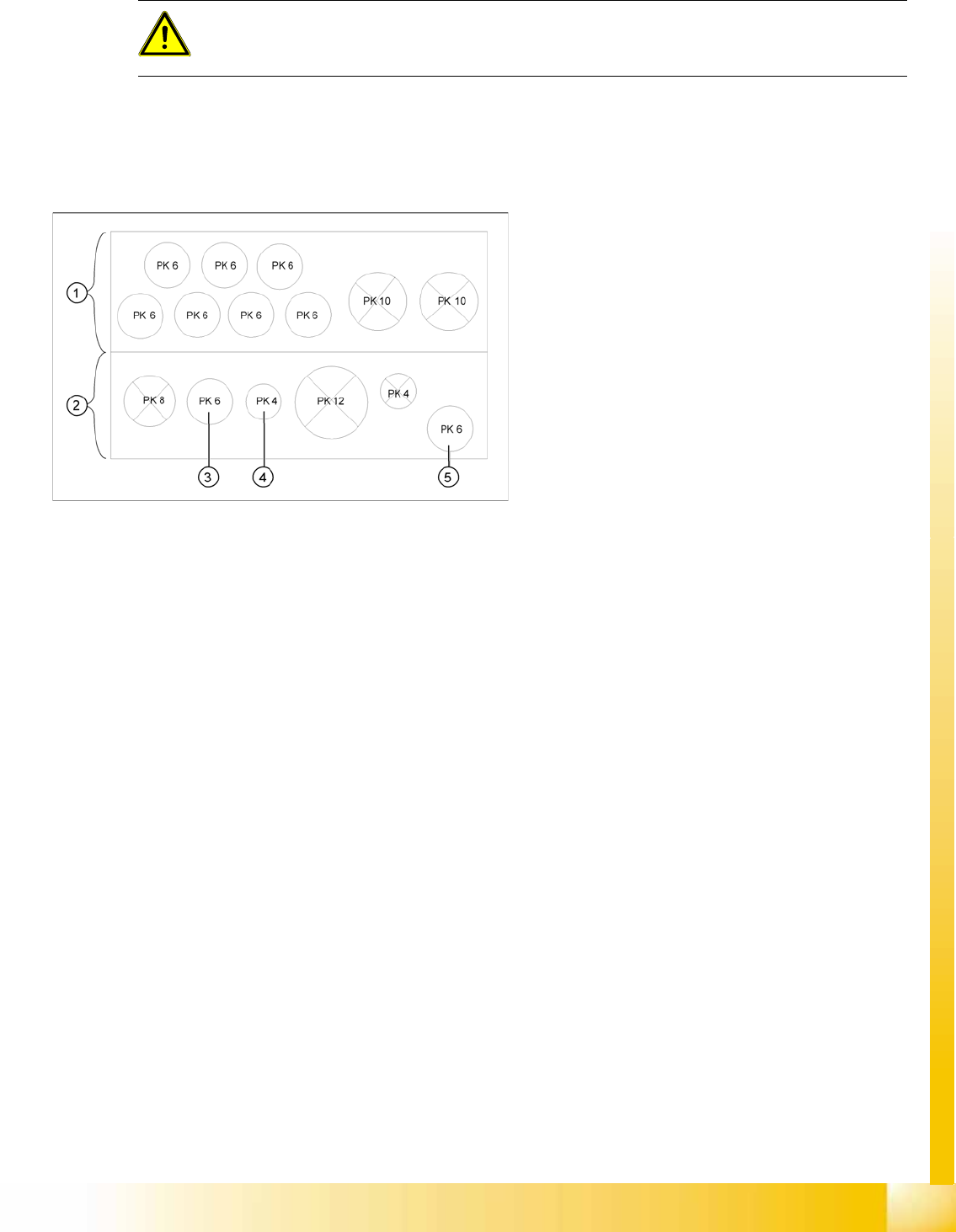
Legend
1. Rear view
2. Front view
3. Connection for holding circuit
4. Connection for return cylinder
5. Connection for pressure control valve
X Connect the flat ribbon cable and the
pneumatic hoses and run correctly.