00196044-05 - sg x und x4i fse_en.pdf - 第529页
Head Modularity Axis Unit A364 Slots in the Axis unit S tudent Guide (FSE) SIPL ACE X Series and X4I Edition 01/2009 EN Head Modularity 533 13.9 Slot s in the Axis unit Further development of the X series, to include the…
Head Modularity
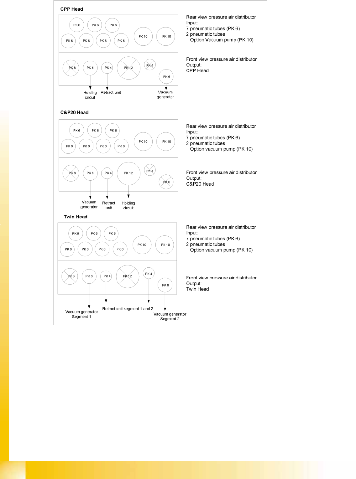
Compressed Air Distributor for the Placement Heads Twin Head
Student Guide (FSE) SIPLACE X Series and X4I
Head Modularity Edition 01/2009 EN
532
13-7: Pneumatic distributor for trailing cable CFK06/

Head Modularity
Axis Unit A364 Slots in the Axis unit
Student Guide (FSE) SIPLACE X Series and X4I
Edition 01/2009 EN Head Modularity
533
13.9 Slots in the Axis unit
Further development of the X series, to include the SW603 and the A364 axis controller board, provides
operators with new head configuration options and axis assignment options on the axis controller board.
General description of the servo and axis controller board assignment
In X series machines, we differentiate between the X2 machine with one axis unit in PA2 and the X3 or
X4 machines with two axis units, one each in PA1 and PA2. In addition, we also have the different head
configurations at the gantries and their assignment of servo and axis boards in the axis units.
Axis controller board assignment:
The following applies for both axis unit 1 and 2:
1. Max. 3 axis boards per axis unit (slot 1-3).
2. Axis board in slot 1 always for the lower value gantry in the placement area
Assignment (from top to bottom) X, Y, star, Z) for TH (X, Y, Z_segment 2, Z_segment 1)
3. Axis board in slot 2 always for the higher value gantry in the placement area
Assignment (from top to bottom) X, Y, star, Z) for TH (X, Y, Z_segment 2, Z_segment 1)
4. The axis controller board in slot 3 for C&P20A is not used.
– For the DLM heads:
A1 DP axis for the lower numbered gantry
A3 DP axis for the higher numbered gantry in the placement area.
– For the TWIN Head DP axis:
A1 for DP_segment 1 and A2 for DP_segment 2
of the lower numbered gantry and A3 for DP_segment 1 and A4 for DP_segment 2 of the higher
numbered gantry.
In relation to the axis controller board in slot 3, one can say that the upper part of the axis controller board
(A1, A2) is assigned to the axis controller board in slot 1, while the lower part of the axis controller board
(A3, A4) is assigned to the axis controller board in slot 2.
Servo board assignment:
The servo boards for the relevant head are the same in the upper and lower part of the axis unit.
13.9.1 Axis Unit A364
Further development of the X series, to include the SW 603 and the A364 axis controller board, provides
operators with new head configuration options and axis assignment options on the axis controller board.
Head Modularity
Slots in the Axis unit Axis Unit A364
Student Guide (FSE) SIPLACE X Series and X4I
Head Modularity Edition 01/2009 EN
534
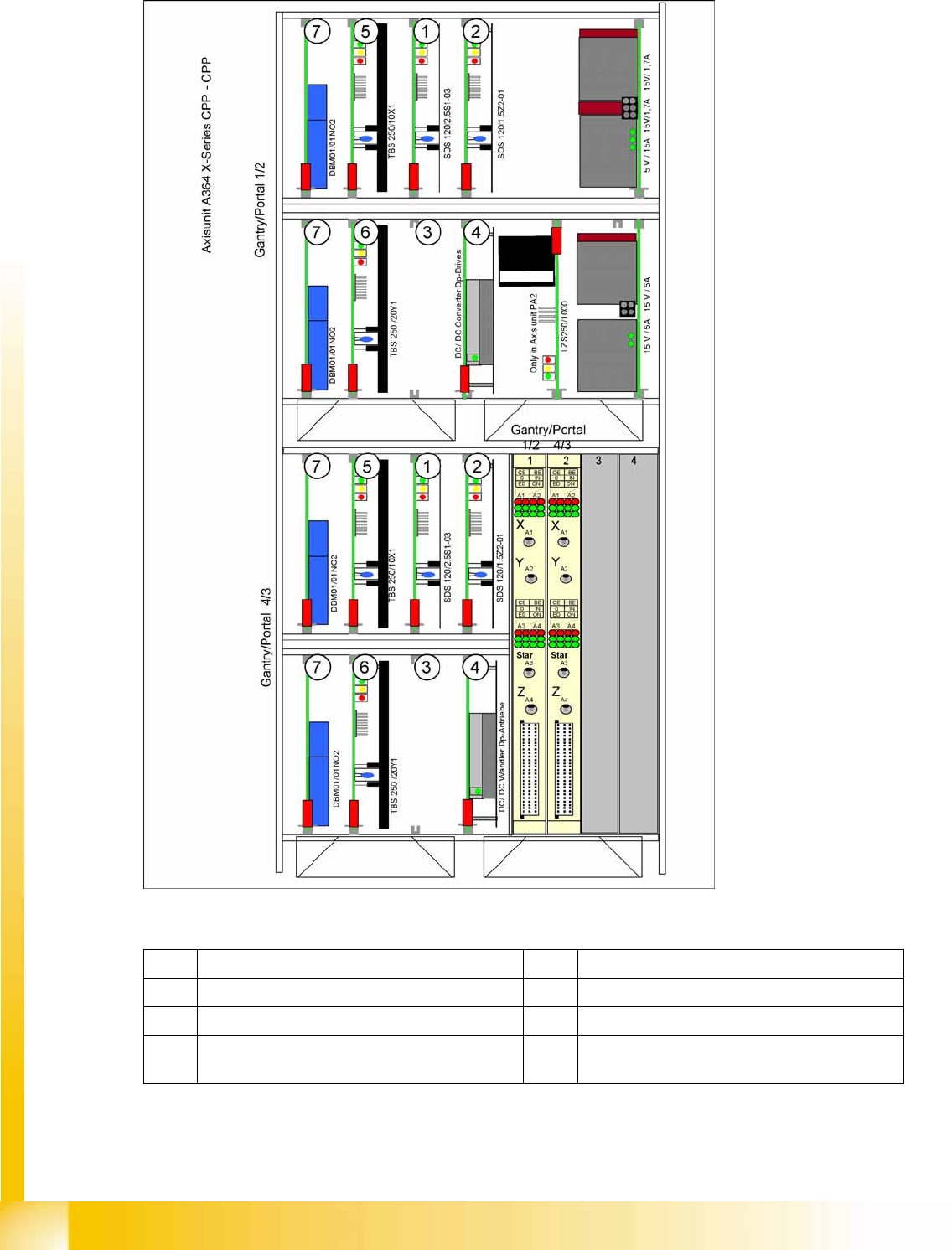
13.9.1.1 Axis Unit A364 with CPP-CPP
Legend
1 Servo amplifier star axis 5 Servo amplifier X axis
2 Servo amplifier Z axis 6 Servo amplifier Y axes
3 Free space 7 Brake board for each X axis and Y axis
4 24V-DC/DC converter - voltage supply for DP
axes