00196044-05 - sg x und x4i fse_en.pdf - 第541页
MTC2 Techni cal Data Overview S tudent Guide (FSE) SIPL ACE X Series and X4I Edition 01/2009 EN MTC2 545 14.1.3 T echnical Data 14.1.3.1 Dimensions, weight, miscellan eous data 14.1.3.2 Electrical Connections 14.1.3.3 No…
MTC2
Overview Occupying and numbering the tower
Student Guide (FSE) SIPLACE X Series and X4I
MTC2 Edition 01/2009 EN
544
After the SIPLACE station has picked up the necessary components out of the waffle pack tray, the WTC
is moved back into the cassette again.
The WTCs are transferred between the lifting axis and the feed axis via defined transfer and removal
positions. Safety queries from the software ensure that the cassettes and WTCs are always in the correct
location when the lifting axis and feed axis are moved.
Both towers can be set up independently of each other. While one tower is being refilled, the second can
continue to supply the SIPLACE station with components. This prevents interruptions to the placement
process. Special waffle pack trays are an exception here, since they can only be set up in one of the
towers.
The MTC2 can be docked onto the SIPLACE station instead of a component trolley. A separate docking
frame accepts the MTC2 and fixes it in place with two alignment pins. The exact position is measured
by two camera fiducials during the SIPLACE station reference run. The MTC2 can be moved on its own
wheels for replacement.
The system is adapted to the different standard heights (Europa and SMEMA) during the initial setup
phase, but can still be changed later without additional tools being required. The height is adjusted with
a crank mechanism when the machine is docked onto the SIPLACE station.
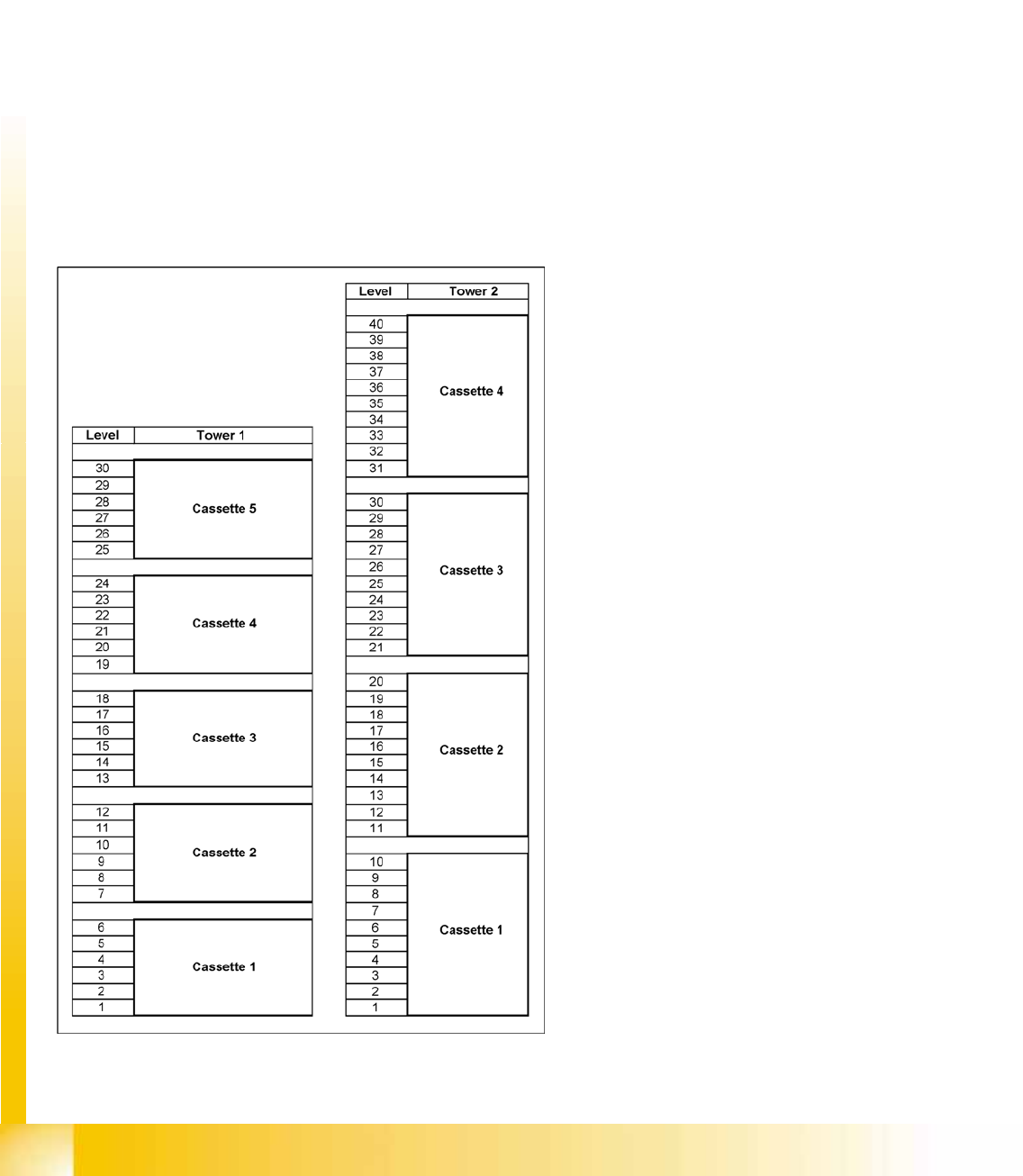
14.1.2 Occupying and numbering the tower
14-3: Numbering of levels in tower 1 and tower 2
You can set up and fully automatically change up
to 100 JEDEC waffle pack trays in WTCs with the
MTC2 on the SIPLACE station. The levels for the
waffle pack trays are numbered for each tower,
from the bottom to the top (1-30 for tower 1 and 1-
40 for tower 2). Only every second or third level is
occupied if higher waffle pack trays are used (high
JEDEC waffle pack trays or special waffle pack
trays).
The lifting axis on tower 1 can accommodate 5
cassettes with up to 6 WTC XLs each. Either two
JEDEC waffle pack trays or any number of special
waffle pack trays can be accommodated in a WTC
XL.
The lifting axis on tower 2 can accommodate 4
cassettes with up to 10 WTCs each. A single
JEDEC waffle pack tray can be accommodated in
a WTC.
MTC2
Technical Data Overview
Student Guide (FSE) SIPLACE X Series and X4I
Edition 01/2009 EN MTC2
545
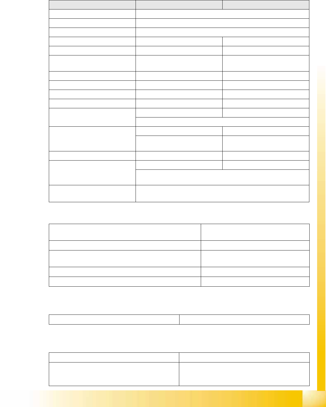
14.1.3 Technical Data
14.1.3.1 Dimensions, weight, miscellaneous data
14.1.3.2 Electrical Connections
14.1.3.3 Noise Emission Information
14.1.3.4 Permitted ambient conditions
Tower 1 (XL) Tower 2
Dimensions (L x W x H) 1340 x 610 x 1490/1660 mm
Weight (basic configuration) approx. 500 kg (incl. cassettes and WTCs)
Weight (set up completely) approx. 534 kg (with components)
Weight (moving mass) approx. 80 kg approx. 43.5 kg
Cassette size (L x W x H) 391.2 x 305.6 x 93.3 mm 352.7 x 154.8 x 133.8 mm
Cassette weight
(fully configured)
approx. 11 kg approx. 7.5 kg
WTC size (L x W x H) 386.5 x 295.8 x 11.1 mm 371 x 146 x 10.1 mm
Pitch between cassettes 96 mm 135 mm
Pitch between levels 12 mm 11.8 mm
Vertical travel 444 mm (1st through 40th WTC) 511.2 mm (1st through 40th WTC)
Horizontal travel approx. 647 mm approx. 638 mm
(between removal and transfer positions)
Storage capacity 30 WTC XL with 40 WTC with
60 JEDEC or 30 special WPTs max.
size
40 JEDEC WPT
Changeover time (over 5 levels) approximately 2 s approximately 1.5 s
Maximum component height
(incl. WTC)
30 mm 15.5 mm
(For WT height > 7.62 mm 1 level must remain free,
For WT height >12.19 mm 2 levels must remain free)
Maximum floor load
(fully configured)
6.93 kg/cm
2
or 356 kg/cm
2
per foot per roller
Supply voltage 3 x 400 V~, 50 Hz (Europe)
3 x 208 V~, 60 Hz (USA)
Total power 1.5 kW
Rated current 2.7 A for 3 x 400 V~
4.2 A for 3 x 208 V~
Fuse rating 3 x 16 A
Rated current consumption by the largest consumer 2 A
Maximum noise level 74 dB (A)
Room temperature between 15°C and 35°C
Humidity 30 - 75%
(on average no higher than 45%, to prevent
condensation on the machine at all times.)
MTC2
Overview Operational Safety
Student Guide (FSE) SIPLACE X Series and X4I
MTC2 Edition 01/2009 EN
546
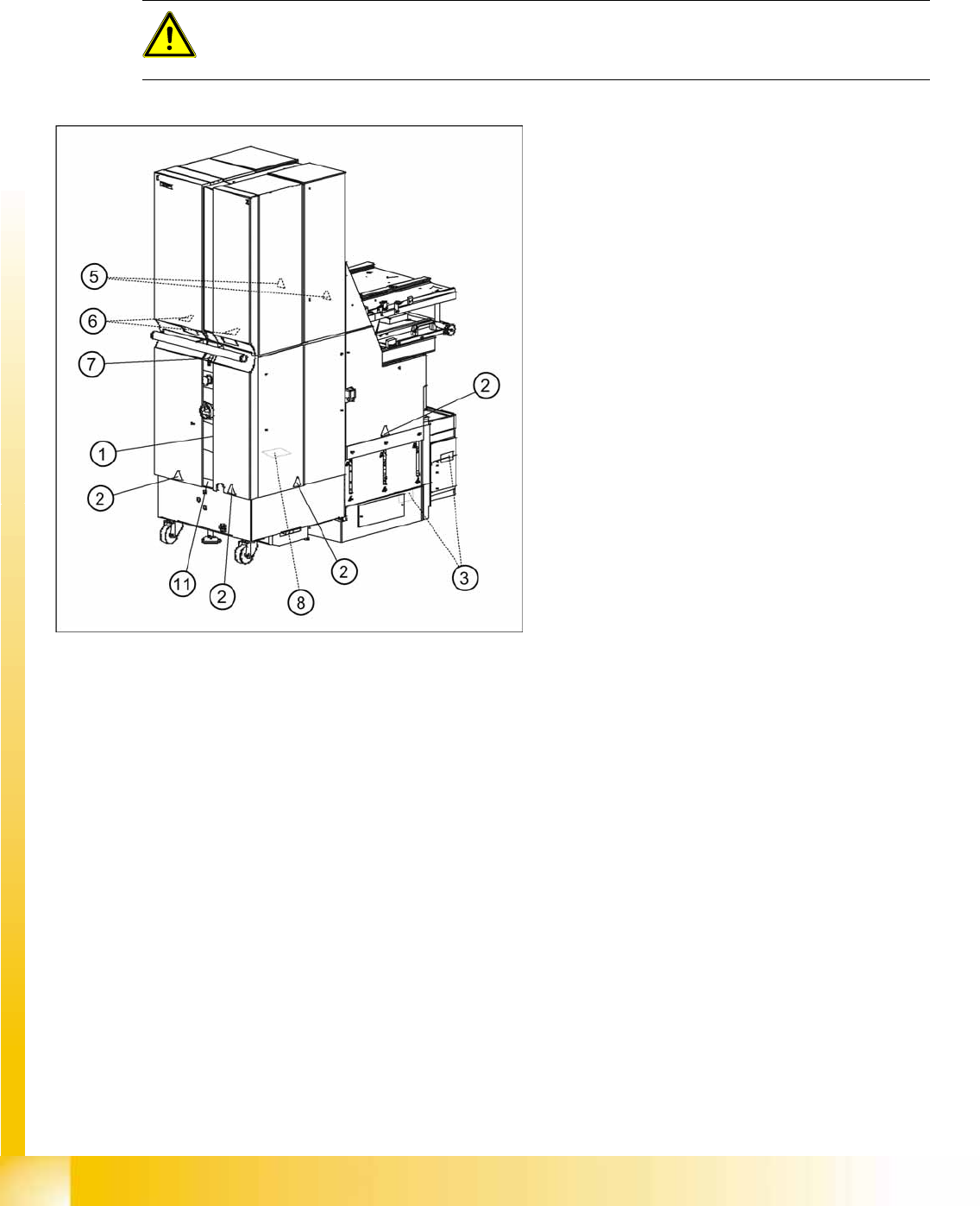
14.1.4 Operational Safety
14.1.4.1 Safety Instructions
Warning and Information Labels on the MTC2
ATTENTION:
The following pages contain only the most important safety information.
X Please observe the safety instructions detailed in the current operating instructions.
14-4: Location of the warning labels on the MTC2 (right-hand side)
Legend
1. Information label below the main switch
2. Warning labels on the enclosures around the
electric parts
3. Warning label by the lifting axis motors
4. Warning labels by the toothed belts of the
lifting axis and feed axis
5. Warning labels in the feeding area and the
lifting frame area
6. Warning labels in the refill area (behind the
protective doors)
7. Information label at the ground terminal
8. Warning labels on the motor controller covers
(below the enclosure)
9. No loads warning by the feed axis
10. Information labels above the guides for the
fork lift truck
11. Information label for the cranking device