00196044-05 - sg x und x4i fse_en.pdf - 第548页
MTC2 Overview Oper ational Safety S tudent Guide (FSE) SI PL ACE X Series and X4I MTC2 Edition 01/2009 EN 552 Protective Door Switches Combination circuit breakers Safety and Signaling Circuit The safety circuit consists…
MTC2
Operational Safety Overview
Student Guide (FSE) SIPLACE X Series and X4I
Edition 01/2009 EN MTC2
551
14.1.4.2 Safety Features
Protective Doors
EMERGENCY STOP button
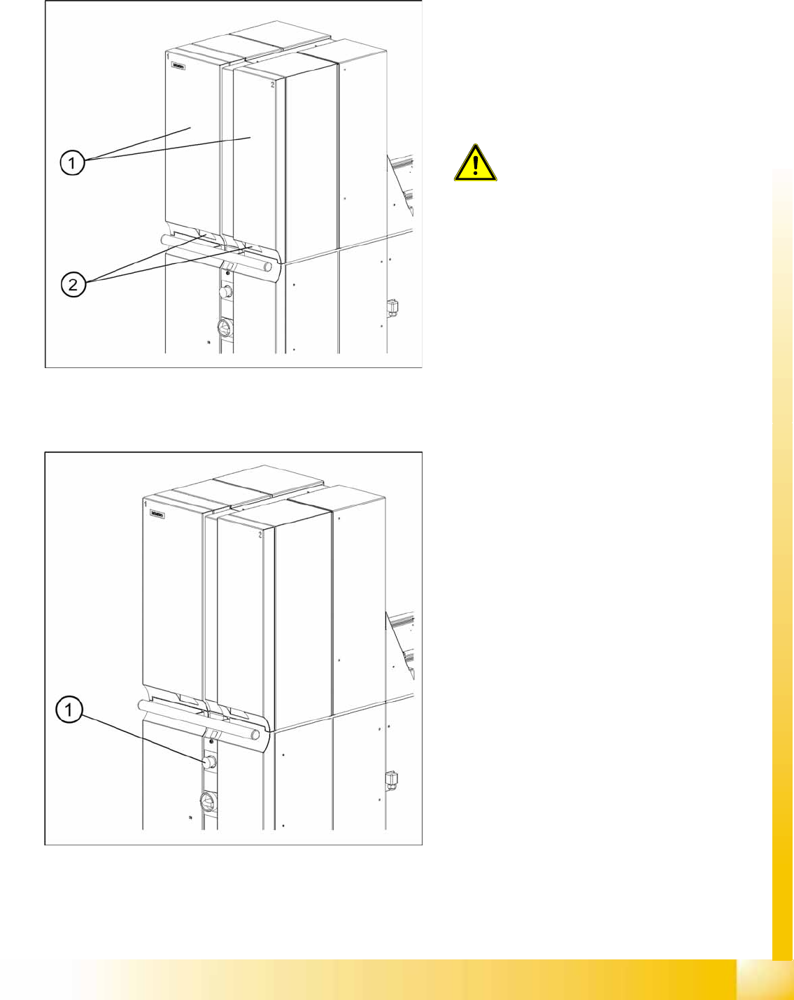
14-18: Protective Doors
Both towers have a protective door. When you
open the protective door, the tower is powered
down. The following error message appears on
your screen:
Tower x: protective door not
closed
The other tower continues to work until it
completes its cycle. Once the protective door is
closed, the cycle must be restarted.
CAUTION:
Do not open the protective doors of the
MTC2 unless you are informed to do so
on the screen of the station computer
or when the MTC2 has been switched
off.
Legend
1. Protective Doors
2. Recessed handles
14-19: Location of the EMERGENCY STOP button
Legend
1. EMERGENCY STOP button
The EMERGENCY STOP button is a self-latching
combination and designed with bypass protection
according to EN 418. This red, mushroom-shaped
button remains depressed when you press it.
When you press the EMERGENCY STOP button,
the entire line, with SIPLACE station and MTC2, is
immediately stopped. Placement is interrupted
and, once the machine is in working order again,
can be resumed or canceled. Watch out for any
incompletely assembled printed circuit boards.
Pressing the EMERGENCY STOP button opens
the two switching contacts of the safety circuits;
the relevant safety combination is triggered. The
intermediate-circuit voltages (500 V) for the
inverters are disconnected. Both the lifting and
feed axes are deactivated while the logic circuitry
of the inverters continues to be supplied with 24 V
DC. The following error message appears on your
screen:
EMERGENCY STOP operated
will be
shown on the screen.
MTC2
Overview Operational Safety
Student Guide (FSE) SIPLACE X Series and X4I
MTC2 Edition 01/2009 EN
552
Protective Door Switches
Combination circuit breakers
Safety and Signaling Circuit
The safety circuit consists of three safety combinations, which work completely independently of each
other. They are used to monitor the following actions:
Actuation of the EMERGENCY STOP button
Opening the protective door of tower 1
Opening the protective door of tower 2
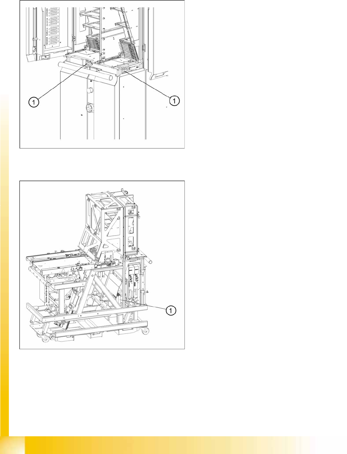
14-20: Position of the protective door switches
These switches check whether the two protective
doors are closed. If the doors are closed, the
safety contact and the signaling contact are
closed. When one of the doors is opened, the
safety circuit and the signaling circuit are opened.
The corresponding safety combination is triggered
and the tower is powered down. The following
error message appears: “Tower x: Protective door
not closed”.
Legend
1. Protective Door Switches
14-21: Position of the combination circuit breakers
The combination circuit breakers are fitted on the
rear of the masterdrive housing. In the event of
malfunctions that are relevant to safety, they are
triggered.
Legend
1. Combination circuit breakers
MTC2
Operational Safety Overview
Student Guide (FSE) SIPLACE X Series and X4I
Edition 01/2009 EN MTC2
553
The two protective doors are each equipped with a protective door switch. These are looped into the
starting circuit of the respective monitoring device.
If the EMERGENCY STOP button is pressed during operation or one of the two protective doors opens,
the relevant safety combination is tripped and the drives are locked via contactors on the electronics
board.
The signaling circuit for the protective door monitoring system is transmitted to the MTC2 controller by
the relevant safety combinations, via normally open contacts.
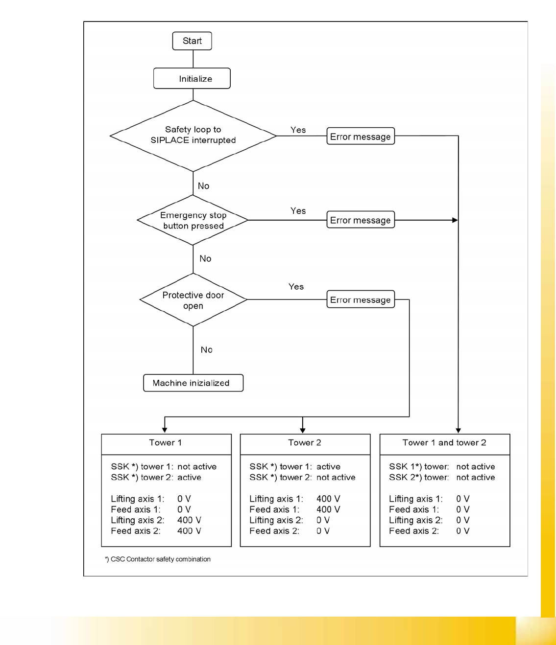
Safety Loops
14-22: Safety Loops