00196044-05 - sg x und x4i fse_en.pdf - 第549页
MTC2 Operational Safety Overview S tudent Guide (FSE) SIPL ACE X Series and X4I Edition 01/2009 EN MTC2 553 The two protective door s are each equipped with a protective door switch. These are looped into the starting ci…
MTC2
Overview Operational Safety
Student Guide (FSE) SIPLACE X Series and X4I
MTC2 Edition 01/2009 EN
552
Protective Door Switches
Combination circuit breakers
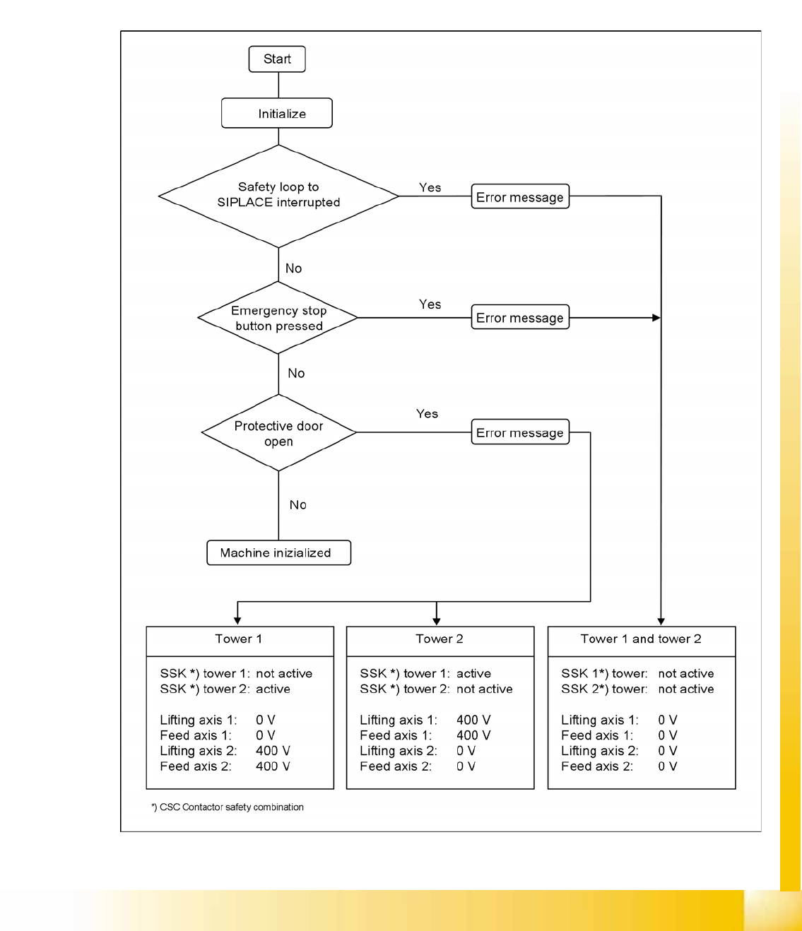
Safety and Signaling Circuit
The safety circuit consists of three safety combinations, which work completely independently of each
other. They are used to monitor the following actions:
Actuation of the EMERGENCY STOP button
Opening the protective door of tower 1
Opening the protective door of tower 2
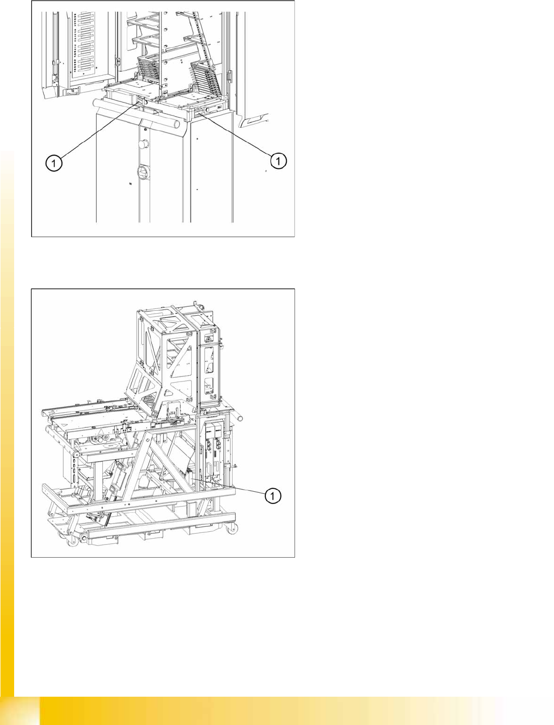
14-20: Position of the protective door switches
These switches check whether the two protective
doors are closed. If the doors are closed, the
safety contact and the signaling contact are
closed. When one of the doors is opened, the
safety circuit and the signaling circuit are opened.
The corresponding safety combination is triggered
and the tower is powered down. The following
error message appears: “Tower x: Protective door
not closed”.
Legend
1. Protective Door Switches
14-21: Position of the combination circuit breakers
The combination circuit breakers are fitted on the
rear of the masterdrive housing. In the event of
malfunctions that are relevant to safety, they are
triggered.
Legend
1. Combination circuit breakers
MTC2
Operational Safety Overview
Student Guide (FSE) SIPLACE X Series and X4I
Edition 01/2009 EN MTC2
553
The two protective doors are each equipped with a protective door switch. These are looped into the
starting circuit of the respective monitoring device.
If the EMERGENCY STOP button is pressed during operation or one of the two protective doors opens,
the relevant safety combination is tripped and the drives are locked via contactors on the electronics
board.
The signaling circuit for the protective door monitoring system is transmitted to the MTC2 controller by
the relevant safety combinations, via normally open contacts.
Safety Loops
14-22: Safety Loops
MTC2
Construction and mode of operation Lifting and Feeder Motors
Student Guide (FSE) SIPLACE X Series and X4I
MTC2 Edition 01/2009 EN
554
14.2 Construction and mode of operation
The MTC2 extends the capacity of a SIPLACE station to supply components by up to 100 JEDEC waffle
pack trays. It has its own controller (C167 controller board) and is integrated into the station computer
software. The setup of the MTC2 is integrated into the line controller software of a system.
Each of the two MTC2 towers has a lifting axis and a feed axis. The lifting axes can be set up with a large
number of waffle pack trays in cassettes and transport these vertically. The feed axes transport waffle
pack trays which have been set up horizontally to the transfer position to the SIPLACE station.
All drive units comprise Masterdrive drive systems:
The servo motors of the lifting axes each drive a spindle via a dual toothed belt, which transports
vertically the cassettes which have been set up. A holding brake in the motors, which is controlled
by the Masterdrive via optocouplers, prevents the axis from moving when the machine is switched
off. The lifting axes remain under control when a position has been reached. The toothed belts are
duplicated for safety reasons and are monitored using inductive sensors.
The servo motors of the feed axes use a toothed belt and belt gear to move a driver, which then
moves the selected WTC horizontally to the transfer position of the SIPLACE station.
Lifting axis
One revolution of the servo motor is equivalent to 4096 pulses or a lift of 10 mm on the spindle.
Feed axis
One revolution on the servo motor is equivalent to 4096 pulses or 27.78 mm on the linear guide.
14.2.1 Lifting and Feeder Motors
NOTE: Same motor types for lifting and feeder motors!
Both lifting axis motors and the two feeder axis motors must be of the same type:
MTC2 version 01 [03011837-01]: Motor type 1 FK6 [00354906-01]
MTC2 version 02 [03011837-02]: Motor type 1 FK7 [03035813-01]
Lifting axis features MTC2 zero series
(Mühlbauer)
MTC2 – version 01
modification 401431:
MTC2 – version 02
modification 401471:
Counterbearing spindle Without With With
Spindle lift P=10 P=10 P=12
Spindle speed 3000 1/min 3000 1/min 2500 1/min
Motor pinion (toothed wheel) 36 teeth 36 teeth 30 teeth
Motor type 1FK6 1FK6 1FK7 or 1FK6
Belt tension 170 ± 5 Hz 200 ± 5 Hz 210 ± 5 Hz