00196044-05 - sg x und x4i fse_en.pdf - 第55页
Overview Siplace X Series Spec ifications (Excerpt) SIPLACE X Series S tudent Guide (FSE) SIPL ACE X Series and X4I Edition 01/2009 EN Overview 55 3.1.3 Siplace X Series Specifications (Excerpt) Specification details Val…
Overview
SIPLACE X Series Configurations
Student Guide (FSE) SIPLACE X Series and X4I
Overview Edition 01/2009 EN
54
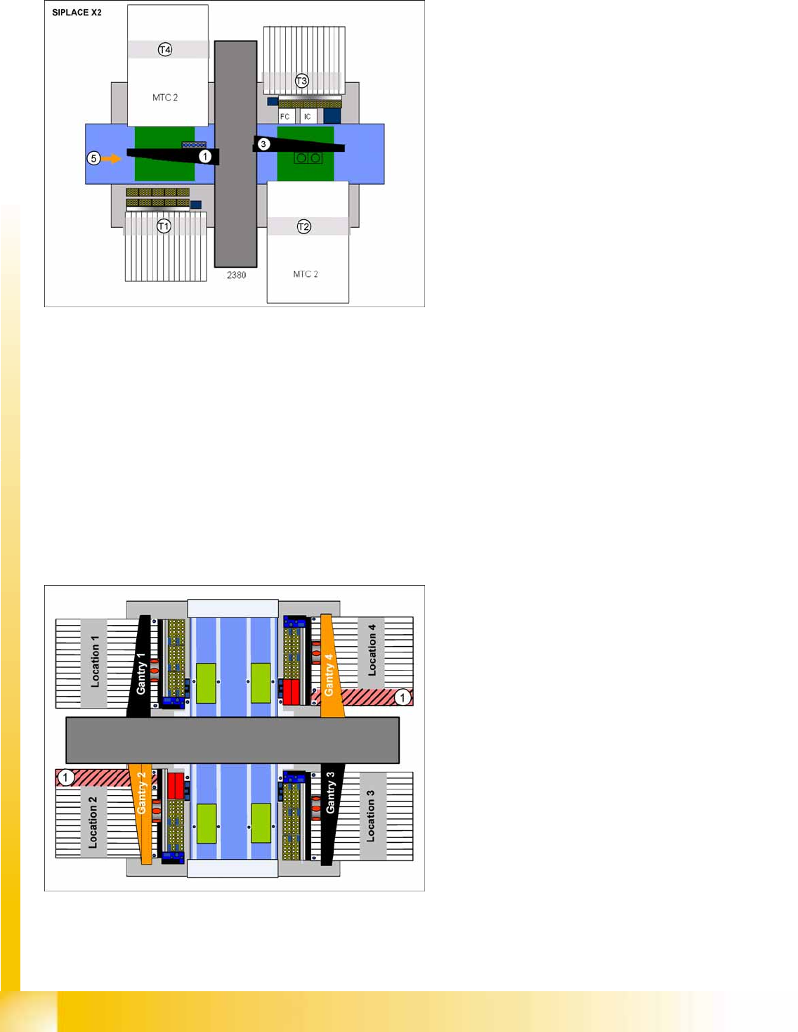
3.1.2.5 SIPLACE X2 Configuration
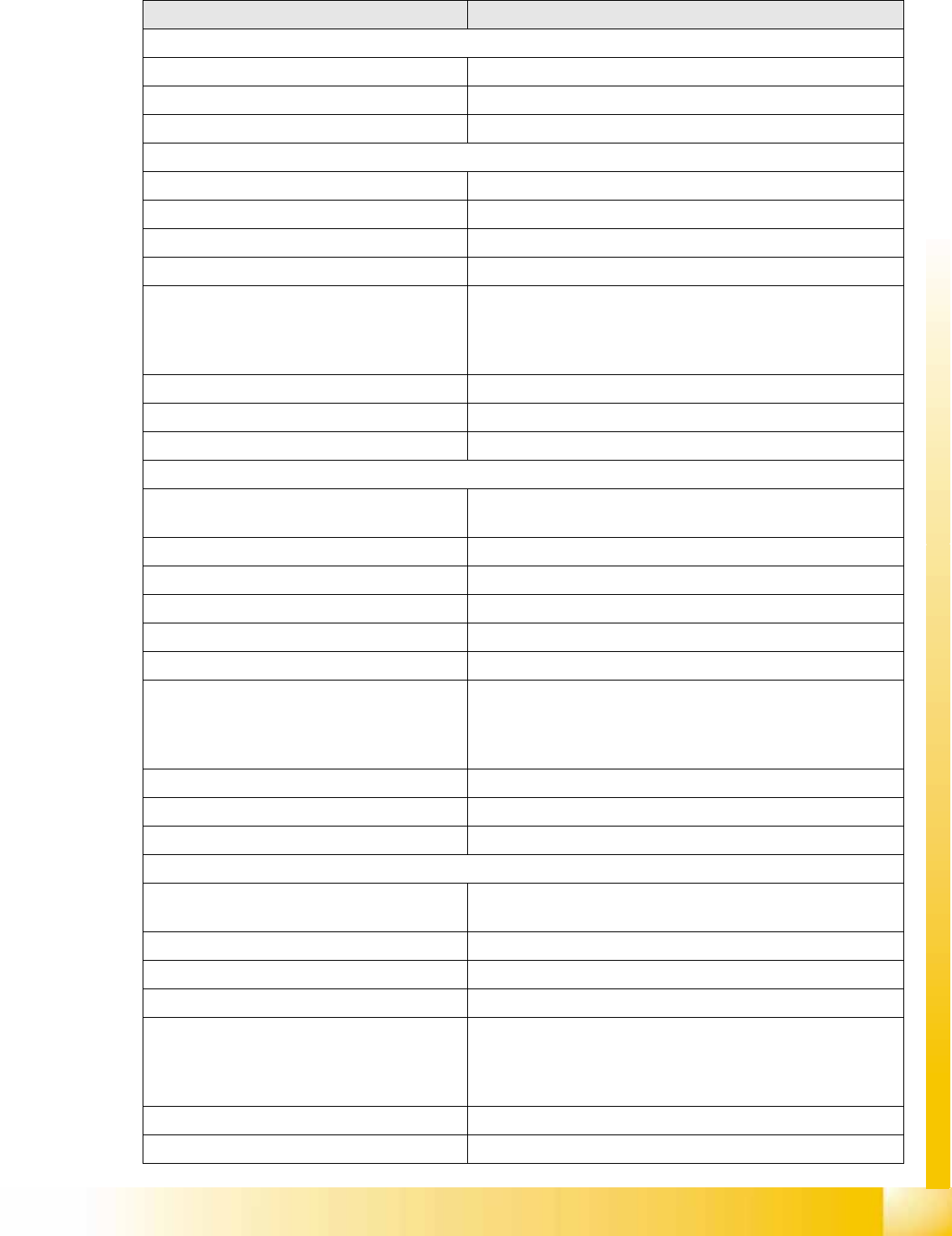
3.1.2.6 SIPLACE X4I - Configuration
The machine is designed and configured for the best possible placement performance. The standard
configuration therefore has 4 gantries, each with one C&P20A placement head. Travel range
optimization has been achieved by rotating gantries 2 and 4. This also enables both gantries to work
independently of one another in the same placement area: I-placement mode.
The following options can be used to further reduce the cycle time in the placement line:
The combined PCB function
A third conveyor lane with shuttle, to replace the productivity lift
A conveyor with 4 lanes (quad lane)
3-7: SIPLACE X2 configuration options
Legend
1, 3: Gantry 1, 3
Gantry 1 with CPP, C&P20A or Twin Head
Gantry 3 with CPP, C&P20A or Twin Head
T1 - T4: Locaton 1 - 4
Location 1, 3: 40 tracks for 8 mm X feeder
Location 2, 4: Changeover table or MTC2
5: Direction of transport , PCB conveyor with 5
areas
Placement area 2 is always equipped with one
placement head which can place higher
components than placement area 1.
Legend
1. Prohibited areas
Due to the rotated gantries 2 and 4, the
marked areas can not be reached. This
applies with both C&P20A and CPP head
configurations.
Overview
Siplace X Series Specifications (Excerpt) SIPLACE X Series
Student Guide (FSE) SIPLACE X Series and X4I
Edition 01/2009 EN Overview
55
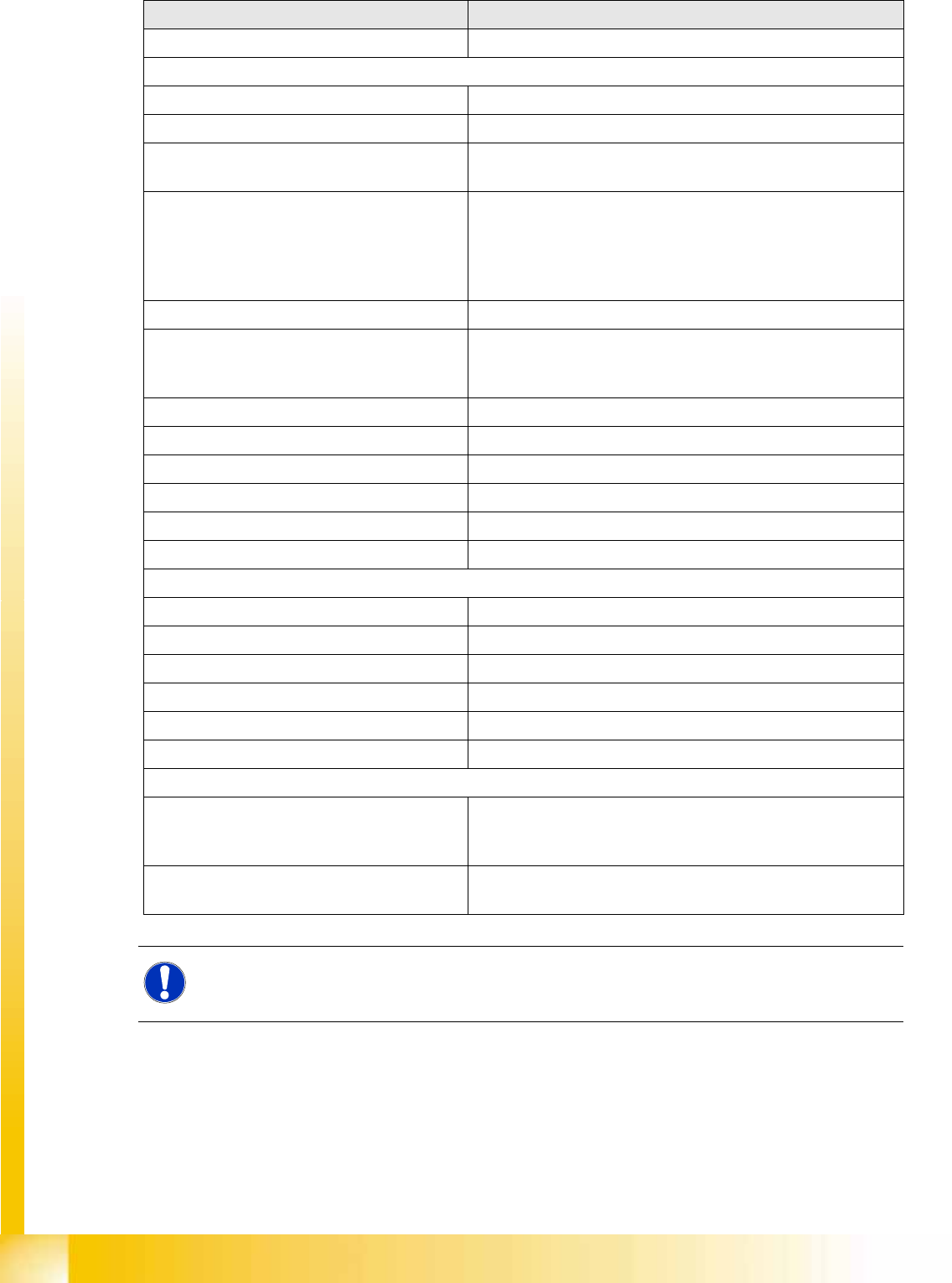
3.1.3 Siplace X Series Specifications (Excerpt)
Specification details Value
Placement performance with example of X4i with C&P20A
Benchmark 120.000 cph
Theoretical value 135.000 cph
IPC value 102.000 cph
C&P20A placement head
Component spectrum 01005 to 2220, Melf, SOT, SOD
Component dimensions (LxW) 6x6 mm
CO height 4.0 mm
CO weight 1 g
Placement accuracy X/Y accuracy:
± 41 μm (3 sigma); ± 55 μm (4 sigma)
Angle accuracy
± 0.5° / (3 sigma); ± 0.7° / (4 sigma)
Placement force 1.5 -4.5 N
Placement mode Collect and Place
Placement performance (benchmark) 30.000 cph
TwinHead placement head
Component spectrum 0201 to SO, PLCC, QFP, socket, connector, BGA, Bare Die,
Shield, FlipChip
Component dimensions (LxW)
in operation with one segment 85x85 mm (125x10 mm)
in operation with both segments 50x50 mm (69x10 mm)
CO height 25 mm
CO weight 30 g, max.100 g
Placement accuracy X/Y accuracy:
± 26 μm / 3σ, ± 35 μm / 4σ ± 22 μm / 3σ, ± 30 μm / 4σ
Angle accuracy
± 0.05° / 3σ, ± 0.07° / 4σ ± 0.05° / 3σ, ± 0.07° / 4σ
Placement force 1-15 N, max.30 N High Force TH
Placement mode Pick and Place
Placement performance (benchmark) 5.000 cph
CPP placement head
Component spectrum 0201 to SO, PLCC, QFP, socket, connector, BGA, Bare Die,
Shield, FlipChip
Component dimensions (LxW) 32x32 mm (C&P mode), 50x40 mm (P&P mode)
CO height CPP_L 6.0 mm, CPP_H 8.5-11.5 mm
CO weight 4 g in C&P mode, 8 g in P&P mode
Placement accuracy ± 55 µm / 4 sigma in C&P mode,
± 45 - ± 55 µm / 4 sigma depending on component camera
(mixed mode)
± 45 µm /4 sigma in P&P mode
Placement force 1-10 N
Placement mode Collect and Place, mixed mode, Pick and Place
Overview
SIPLACE X Series Siplace X Series Specifications (Excerpt)
Student Guide (FSE) SIPLACE X Series and X4I
Overview Edition 01/2009 EN
56
Placement performance (benchmark) 23.500 CO/h in C&P mode, 15000 CO/h in P&P mode
Locations
Number of changeover tables 4
Number of slots for 8 mm X feeder per table 40
Number of slots for 8 mm X feeder per table,
location 2/4 for X4I
34
Feeder types X feeder 8-88 mm
LDU (Linear Dipping Unit)
Label presenter
Adapter X feeders
Reject module
MTC2 location 2/4
Conveyor systems Single conveyor
Dual conveyor
Quad lane conveyor
PCB changeover time < 2.5 s
PCB weight 3 kg
Minimum distance to PCB 3.0 mm
PCB thickness 0.3 – 4.5 mm
Conveyor speed 50-450 mm/s
Fixed conveyor sides Right, left, outer
Conveyor widths
Single conveyor Standard 460 mm, max. 533 mm
Dual conveyor Standard 216 mm, max. 250 mm
Flexible dual conveyor as single conveyor Standard 380 mm, max. 450 mm
Quad lane conveyor 114 mm
PCB lengths Standard 450 mm (X4I max. 380 mm)
"Long Board" option max. 610 mm
Machine connection values
Electrical Connections 3 x 200 V~ ± 5 %; 50/60 Hz (Japan)
3 x 208 V~ ± 5 %; 50/60 Hz (U.S.A)
3 x 400 V~ ± 5 %; 50/60 Hz (Europe)
Pneumatic connection values min. 0.5 MPa = 5.0 bar
max.1.0 MPa = 10 bar
NOTE:
These values are only an excerpt from the specifications! The full specifications can be found in
the operating manual or in the specification documentation for the X series machines!
Specification details Value