00196044-05 - sg x und x4i fse_en.pdf - 第551页
MTC2 Incorporating the MTC in the SIPLACE station Construction and mode of operation S tudent Guide (FSE) SIPL ACE X Series and X4I Edition 01/2009 EN MTC2 555 14.2.2 Incorporatin g the MTC in the SIPLACE st ation 14-23:…
MTC2
Construction and mode of operation Lifting and Feeder Motors
Student Guide (FSE) SIPLACE X Series and X4I
MTC2 Edition 01/2009 EN
554
14.2 Construction and mode of operation
The MTC2 extends the capacity of a SIPLACE station to supply components by up to 100 JEDEC waffle
pack trays. It has its own controller (C167 controller board) and is integrated into the station computer
software. The setup of the MTC2 is integrated into the line controller software of a system.
Each of the two MTC2 towers has a lifting axis and a feed axis. The lifting axes can be set up with a large
number of waffle pack trays in cassettes and transport these vertically. The feed axes transport waffle
pack trays which have been set up horizontally to the transfer position to the SIPLACE station.
All drive units comprise Masterdrive drive systems:
The servo motors of the lifting axes each drive a spindle via a dual toothed belt, which transports
vertically the cassettes which have been set up. A holding brake in the motors, which is controlled
by the Masterdrive via optocouplers, prevents the axis from moving when the machine is switched
off. The lifting axes remain under control when a position has been reached. The toothed belts are
duplicated for safety reasons and are monitored using inductive sensors.
The servo motors of the feed axes use a toothed belt and belt gear to move a driver, which then
moves the selected WTC horizontally to the transfer position of the SIPLACE station.
Lifting axis
One revolution of the servo motor is equivalent to 4096 pulses or a lift of 10 mm on the spindle.
Feed axis
One revolution on the servo motor is equivalent to 4096 pulses or 27.78 mm on the linear guide.
14.2.1 Lifting and Feeder Motors
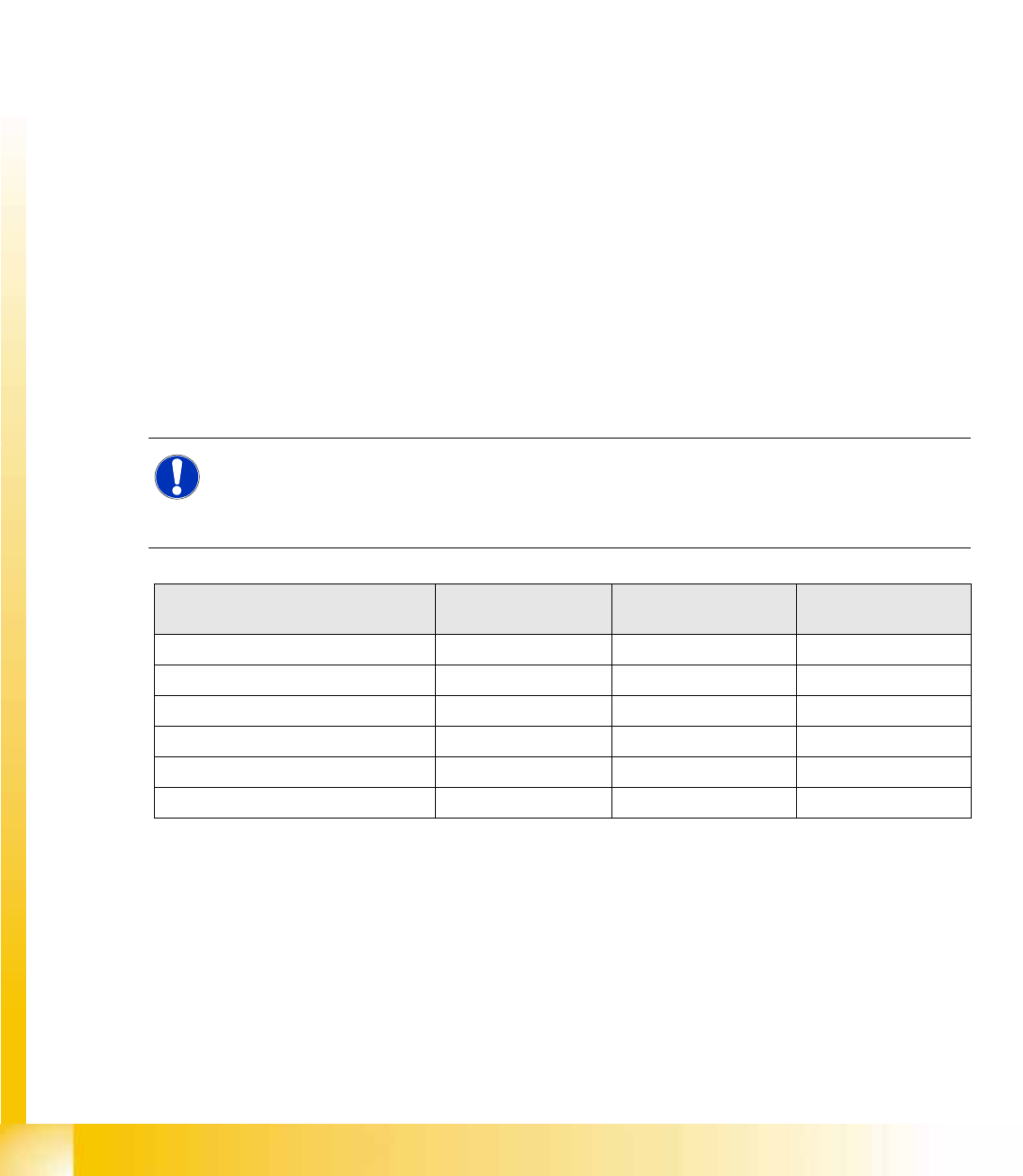
NOTE: Same motor types for lifting and feeder motors!
Both lifting axis motors and the two feeder axis motors must be of the same type:
MTC2 version 01 [03011837-01]: Motor type 1 FK6 [00354906-01]
MTC2 version 02 [03011837-02]: Motor type 1 FK7 [03035813-01]
Lifting axis features MTC2 zero series
(Mühlbauer)
MTC2 – version 01
modification 401431:
MTC2 – version 02
modification 401471:
Counterbearing spindle Without With With
Spindle lift P=10 P=10 P=12
Spindle speed 3000 1/min 3000 1/min 2500 1/min
Motor pinion (toothed wheel) 36 teeth 36 teeth 30 teeth
Motor type 1FK6 1FK6 1FK7 or 1FK6
Belt tension 170 ± 5 Hz 200 ± 5 Hz 210 ± 5 Hz
MTC2
Incorporating the MTC in the SIPLACE station Construction and mode of operation
Student Guide (FSE) SIPLACE X Series and X4I
Edition 01/2009 EN MTC2
555
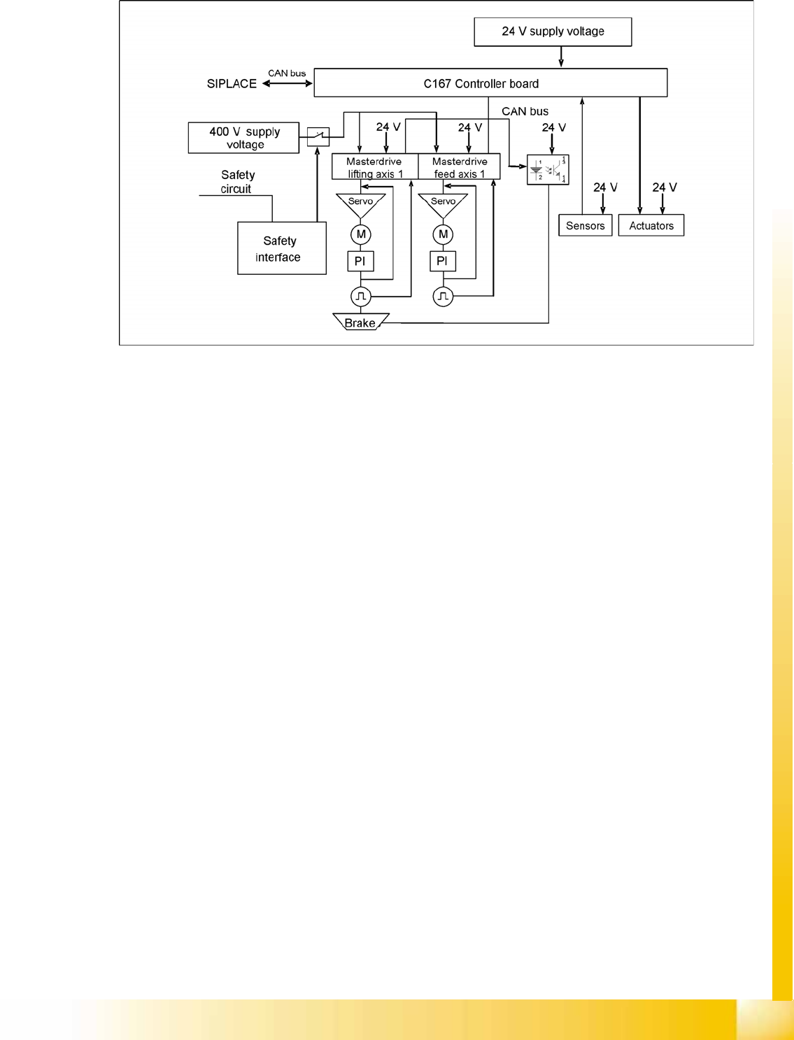
14.2.2 Incorporating the MTC in the SIPLACE station
14-23: MTC2 interfaces and power supply (shown for tower 1)
CAN Bus
This interface is used for all commands which are sent by the machine controller of the SIPLACE station.
Example: Reference position run and transfer of set-up data.
400 V power supply
The MTC2 is supplied externally with 400 V (USA/Japan: 208/204 V).
EMERGENCY STOP interface
The MTC2 is incorporated into the safety circuit of the SIPLACE station. This provides feedback in the
form of a protective circuit voltage of 24 V. This protective circuit voltage switches the relevant
combination circuit breaker and thus the 400 V of the inverters for the Masterdrives.
The contactors switch off the servo voltage (400 V) and also immediately switch off the power supply to
the brake.
The signaling contact (make contact) of the EMERGENCY STOP button is connected to the input of the
SIPLACE safety signalling system. The break contact interrupts the 24 V protective circuit voltage of the
SIPLACE machine.
If the EMERGENCY STOP circuit in a machine is interrupted (EMERGENCY STOP button), the master
drives of the MTC2 will trip. Both systems are then not under power.
When one of the two MTC2 protective doors is opened, only the control voltage of the relevant tower
falls.

MTC2
Construction and mode of operation Reference position run
Student Guide (FSE) SIPLACE X Series and X4I
MTC2 Edition 01/2009 EN
556
14.2.3 Reference position run
When the MTC2 is switched on, a reference position run needs to be performed for the servo axes, as
for the SIPLACE station. If the MTC2 remains switched on when the SIPLACE station is switched off and
back on, it will report that it has already been referenced.
During the reference position run, both towers move into their reference positions simultaneously. The
two feed axes are moved first and then the two lifting axes.
Each axis first moves to its physical home position then checks the position of the two software limit
switches and finally stops in the software zero position (this corresponds to the relevant zero offset of
the physical home position). The positions adopted by the axes are then defined as reference and
calibration positions.
The reference run for an individual axis is performed as follows:
The current zero offset is sent to the Masterdrive.
The controller queries the "neutral position" of the light barrier and waits for a rising edge.
If the axis is already positioned in the light barrier, it issues a "HIGH" signal. The axis moves in a
positive direction until the light barrier delivers a falling edge. The axis then moves in the negative
direction again.
If the axis is not positioned in the light barrier, it issues a "LOW" signal. The axis moves in a negative
direction.
The axis moves in the negative direction until the light barrier delivers the necessary rising edge and
the first rotor zero position (index) has been found.
This procedure is necessary, since the zero pulses of the resolver angular encoder are repeated with
each revolution and thus appear several times within the possible travel range.
The axes move to both software limit switches in the maximum and minimum positions to within a
few millimeters, to check the saved data.
Finally, they move to the current zero offset.
When the axes have moved to all four reference positions, the SIPLACE station searches for the two
fiducials on the feed axes. The position which is found is used later to define the pick-up position of
components. The fiducials must be available in the MVS file of the line computer.
ATTENTION:
If the axes are not moved completely to the software limit switches and an error message
appears on the screen for the motor controllers (master drive), one of the axes must be
calibrated again.