00196044-05 - sg x und x4i fse_en.pdf - 第562页
MTC2 Construction and mode of operation General Work Before Starting the MTC2 S tudent Guide (FSE) SI PL ACE X Series and X4I MTC2 Edition 01/2009 EN 566 14.2.7 General Work Before St arting the MT C2 Setting the basic…
MTC2
Installation of MTC2 Construction and mode of operation
Student Guide (FSE) SIPLACE X Series and X4I
Edition 01/2009 EN MTC2
565
14.2.6 Installation of MTC2
In the installation manual the modification is described for a HF machine. The cables aren't available to
newer HF/HF3 and at the SIPLACE X machines at the side of the machine. All cables which go to the
docking frame are in the machine frame and must be attached according to the cable name.
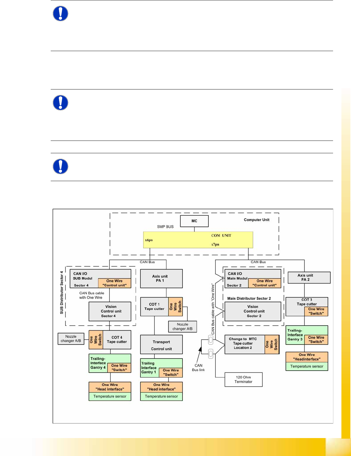
The CAN Bus bridge is needed either at location 2 or 4, depending on the location at which you install
the MTC2.
14-30: Additional CAN Bus bridge for MTC2, if one wire bus has not been realized with a CAT5 cable
NOTE:
If you change the changeover table to an MTC2 at location 2 and/or 4 of a SIPLACE HF/HF3 or
SIPLACE X machine, you will also need to change the whole docking unit (time needed approx.
1 hour).
X Installation manual: Conversion of component trolley to MTC2 (00193897-01.pdf / German,
English)
NOTE:
The HF machines with the series number A 001 and the SIPLACE X machines are equipped
with a "One Wire bus" which is integrated in the Can bus. If you install an MTC2 on these
machines, you must bridge the CAN Bus cable before the docking frame of the MTC.
Reason: The wiring in the docking frame can transmit the CAN Bus signals but not the one wire
signals.
NOTE:
The CAN Bus link is necessary, if the one wire cable integrated into the CAN Bus cable. When
the One Wire Bus installed with CAT5 cable, the CAN Bus link is not necessary.
MTC2
Construction and mode of operation General Work Before Starting the MTC2
Student Guide (FSE) SIPLACE X Series and X4I
MTC2 Edition 01/2009 EN
566
14.2.7 General Work Before Starting the MTC2
Setting the basic height
Installing the safety cover for the lifting axis
Docking
Undocking
14.2.8 Placement Functions
14.2.8.1 Main View with MTC2
NOTE:
see User manual 00193634-01_de.pdf / 00193635-01_eng.pdf.
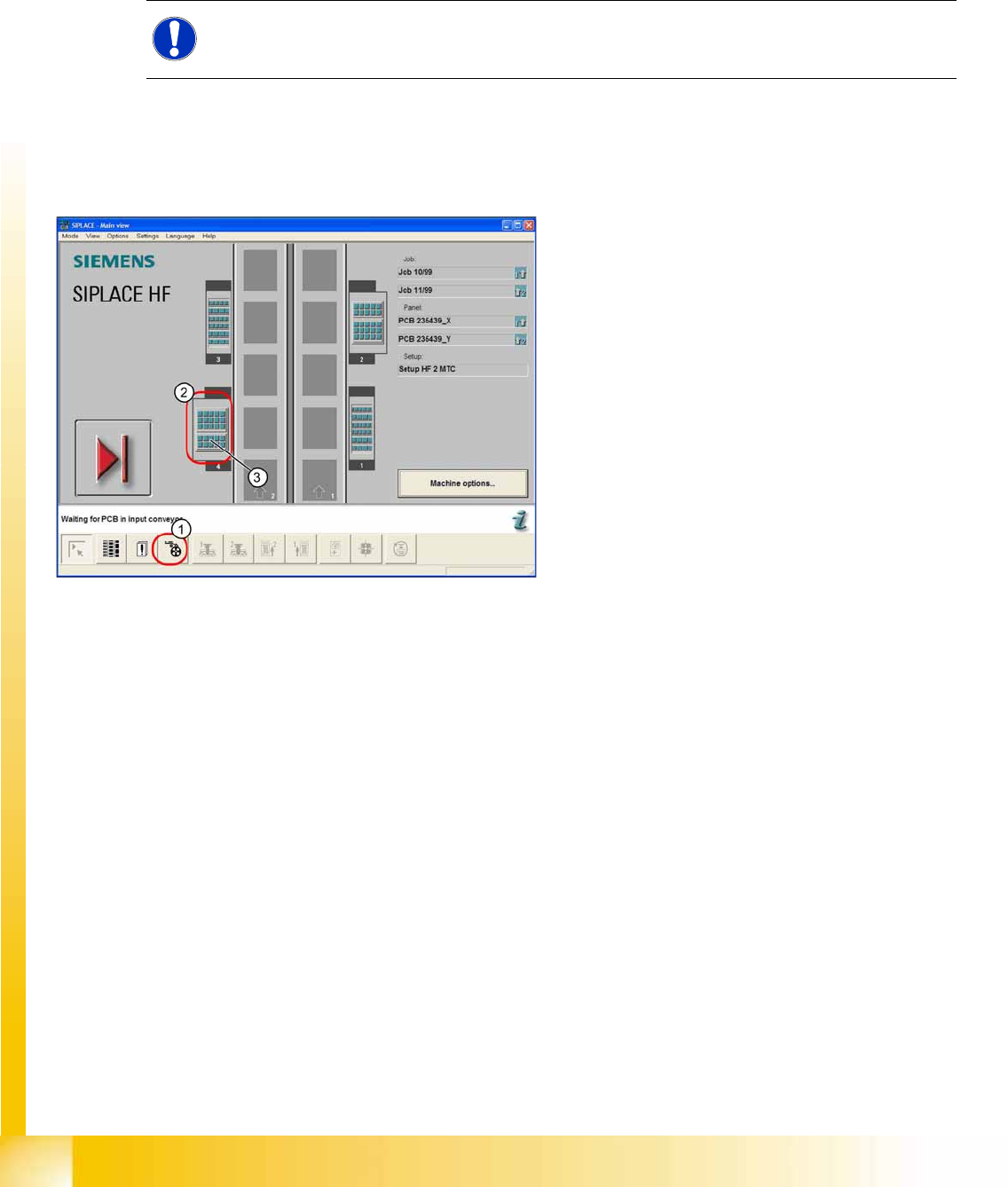
14-31: Main view of the SIPLACE HF with MTC2 at locations and 4
Legend
1. "Feeders" view
2. MTC2 at location 4
3. MTC 2 setup, towers 1 and 2
MTC2
Placement Functions Construction and mode of operation
Student Guide (FSE) SIPLACE X Series and X4I
Edition 01/2009 EN MTC2
567
14.2.8.2 MTC2 - Placement Functions
In the toolbar of the main view, select the icon for the menu function
Feeders
.
The user interface will switch to the
Empty tracks
view, when the
Feeders
menu is called up for the first
time, after the station computer software has been started.
Select the icon for the MTC2 at location 2 or the icon for the MTC2 at location 4.
The
Matrix-tray changer
view will be shown for the selected location.
See also:
J
14.2.8.3 "Matrix-tray changer" view (Example: location 2) [
J
567]
J
14.2.8.1 Main View with MTC2 [
J
566]
14.2.8.3 "Matrix-tray changer" view (Example: location 2)
NOTE:
The icon for the MTC2 at the relevant location is only displayed if an MTC2 is available there.
NOTE:
If a setup is available for an MTC2 , it will be displayed in the main view of the diagram for the
relevant MTC2 .
Select this to open the
Matrix-tray changer
view for the MTC2 at the selected location.
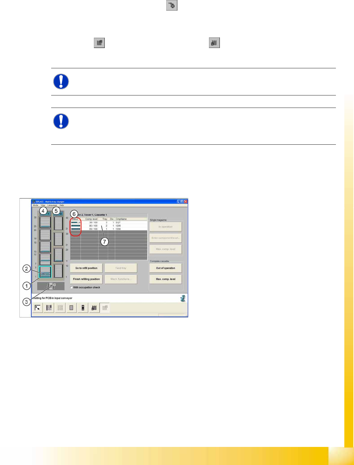
14-32: "Matrix-tray changer" view
Legend
1. Selected cassette
2. Levels in the cassette
3. View of the location
4. Status indicator for tower 1
5. Status indicator for tower 2
6. Display of component level and occupancy of
the selected cassette
7. Selected list entry for a level