00196044-05 - sg x und x4i fse_en.pdf - 第57页
Overview Overview of Placement Head Component Heights Overview of Compone nts S tudent Guide (FSE) SIPL ACE X Series and X4I Edition 01/2009 EN Overview 57 3.1.4 Overview of Placement Head Component Heights 3.2 Overview …
Overview
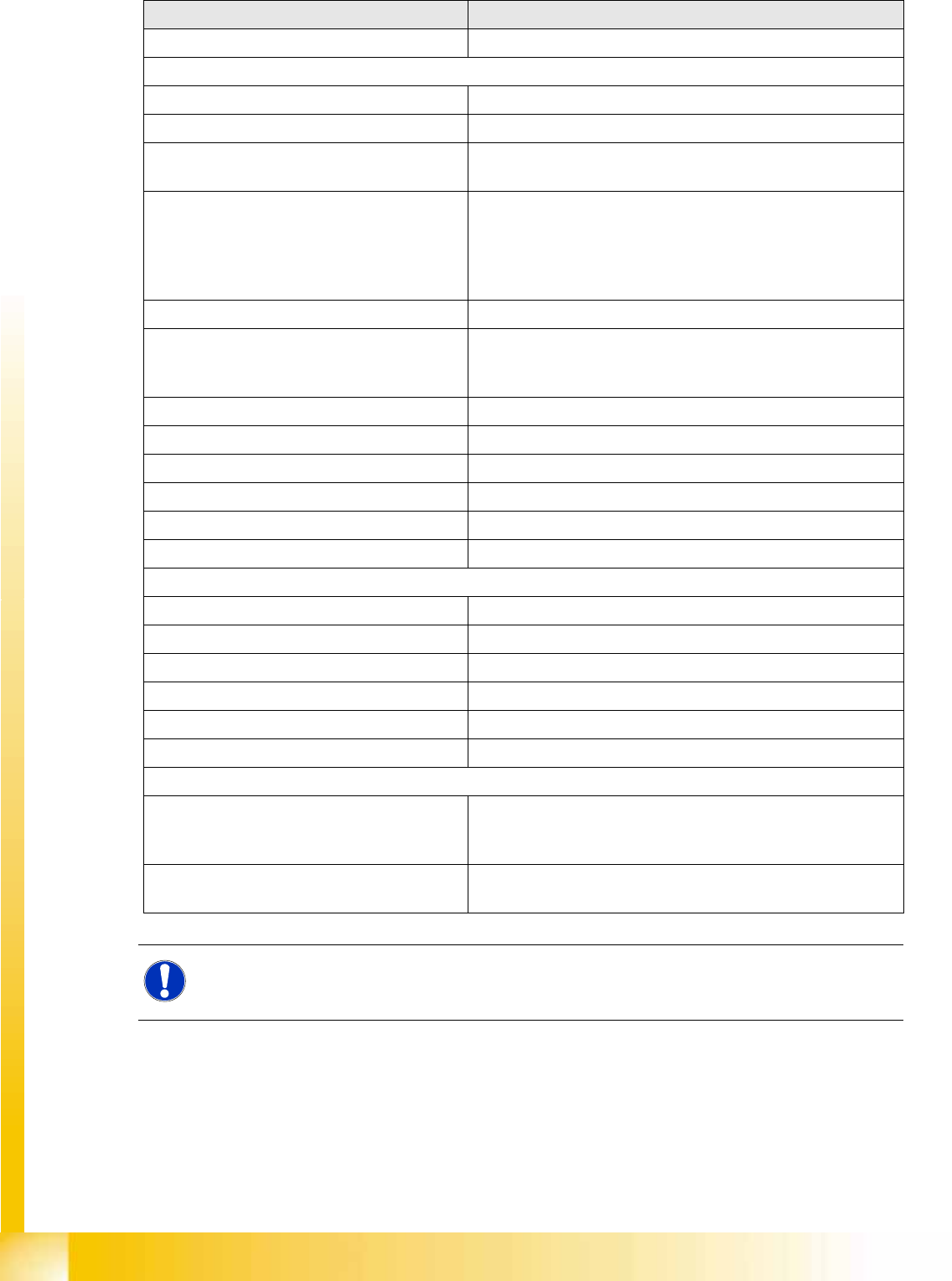
SIPLACE X Series Siplace X Series Specifications (Excerpt)
Student Guide (FSE) SIPLACE X Series and X4I
Overview Edition 01/2009 EN
56
Placement performance (benchmark) 23.500 CO/h in C&P mode, 15000 CO/h in P&P mode
Locations
Number of changeover tables 4
Number of slots for 8 mm X feeder per table 40
Number of slots for 8 mm X feeder per table,
location 2/4 for X4I
34
Feeder types X feeder 8-88 mm
LDU (Linear Dipping Unit)
Label presenter
Adapter X feeders
Reject module
MTC2 location 2/4
Conveyor systems Single conveyor
Dual conveyor
Quad lane conveyor
PCB changeover time < 2.5 s
PCB weight 3 kg
Minimum distance to PCB 3.0 mm
PCB thickness 0.3 – 4.5 mm
Conveyor speed 50-450 mm/s
Fixed conveyor sides Right, left, outer
Conveyor widths
Single conveyor Standard 460 mm, max. 533 mm
Dual conveyor Standard 216 mm, max. 250 mm
Flexible dual conveyor as single conveyor Standard 380 mm, max. 450 mm
Quad lane conveyor 114 mm
PCB lengths Standard 450 mm (X4I max. 380 mm)
"Long Board" option max. 610 mm
Machine connection values
Electrical Connections 3 x 200 V~ ± 5 %; 50/60 Hz (Japan)
3 x 208 V~ ± 5 %; 50/60 Hz (U.S.A)
3 x 400 V~ ± 5 %; 50/60 Hz (Europe)
Pneumatic connection values min. 0.5 MPa = 5.0 bar
max.1.0 MPa = 10 bar
NOTE:
These values are only an excerpt from the specifications! The full specifications can be found in
the operating manual or in the specification documentation for the X series machines!
Specification details Value
Overview
Overview of Placement Head Component Heights Overview of Components
Student Guide (FSE) SIPLACE X Series and X4I
Edition 01/2009 EN Overview
57
3.1.4 Overview of Placement Head Component Heights
3.2 Overview of Components
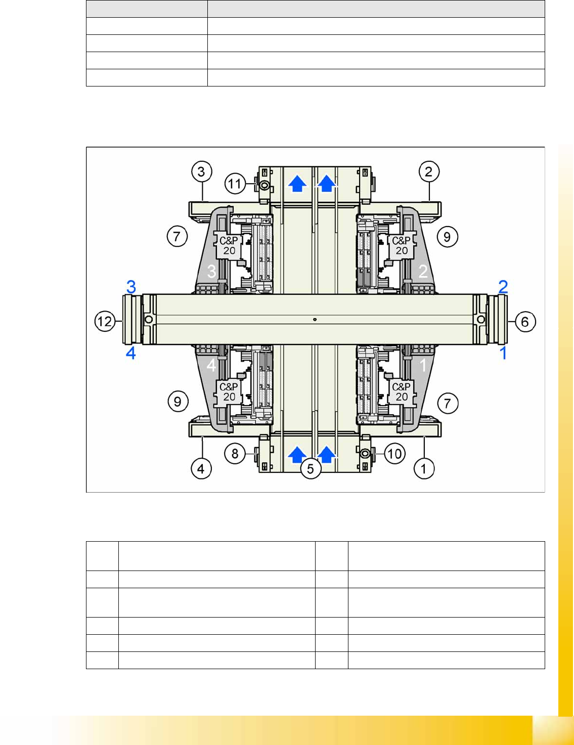
3-8: SIPLACE X4I - top view
Legend
Placement heads Maximum component height
CPP_L 8.5 mm (11.5 mm on request)
CPP_H 6.0 mm
C&P20A 4.0 mm
Twin Head 25.0 mm
1 Sector 1 7 Location for component table 40 tracks, each
with 8 mm X feeder
2 Sector 2 (main distributor) 8 Computer unit
3 Sector 3 9 Location for component table 34 tracks, each
with 8 mm X feeder
4 Sector 4 (subdistributor) 10 Axis unit placement area 1 (PA1)
5 Transport direction 11 Axis unit placement area 2 (PA2)
6 Pneumatic unit & conveyor control 12 Power supply unit
Overview
Overview of Components Power supply
Student Guide (FSE) SIPLACE X Series and X4I
Overview Edition 01/2009 EN
58
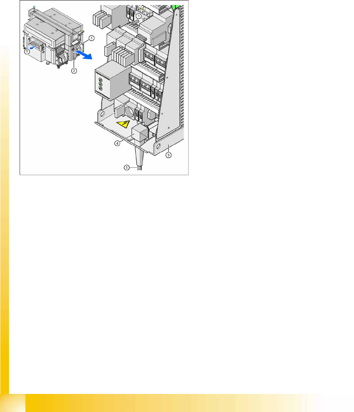
3.2.1 Power supply
The main power supply unit is mounted on a compact rack unit and is located on the left in the middle
section of the machine. From outside, you can only see the red main switch.
A lockable door prevents access to the power supply.
3.2.1.1 Overview of Voltages in the Power Supply Unit
3-9: Power supply
Legend
1. Main switch
2. Cover on the power supply unit
3. Power supply unit
4. Bracket for the cable fixture
5. Mains connection cable
T = PCB transport direction