00196044-05 - sg x und x4i fse_en.pdf - 第58页
Overview Overview of Components Power supply S tudent Guide (FSE) SI PL ACE X Series and X4I Overview Edition 01/2009 EN 58 3.2.1 Power supply The main power supply unit is mounted on a compact rack unit and is located o…
Overview
Overview of Placement Head Component Heights Overview of Components
Student Guide (FSE) SIPLACE X Series and X4I
Edition 01/2009 EN Overview
57
3.1.4 Overview of Placement Head Component Heights
3.2 Overview of Components
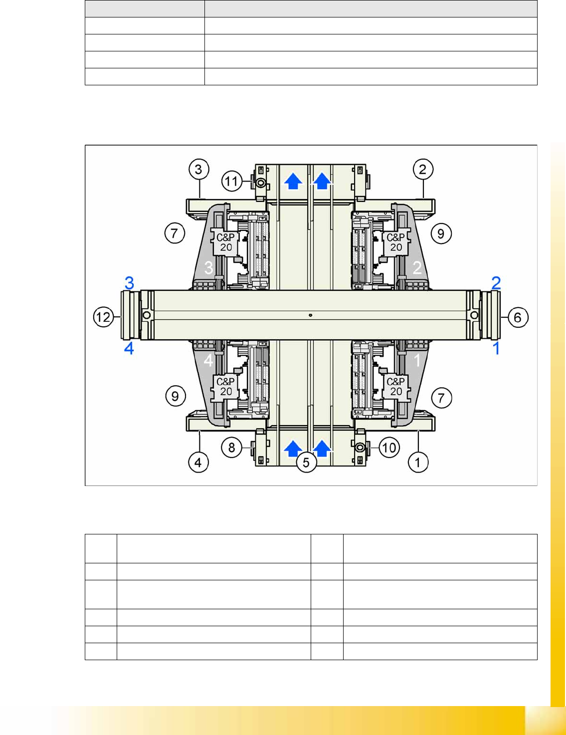
3-8: SIPLACE X4I - top view
Legend
Placement heads Maximum component height
CPP_L 8.5 mm (11.5 mm on request)
CPP_H 6.0 mm
C&P20A 4.0 mm
Twin Head 25.0 mm
1 Sector 1 7 Location for component table 40 tracks, each
with 8 mm X feeder
2 Sector 2 (main distributor) 8 Computer unit
3 Sector 3 9 Location for component table 34 tracks, each
with 8 mm X feeder
4 Sector 4 (subdistributor) 10 Axis unit placement area 1 (PA1)
5 Transport direction 11 Axis unit placement area 2 (PA2)
6 Pneumatic unit & conveyor control 12 Power supply unit
Overview
Overview of Components Power supply
Student Guide (FSE) SIPLACE X Series and X4I
Overview Edition 01/2009 EN
58
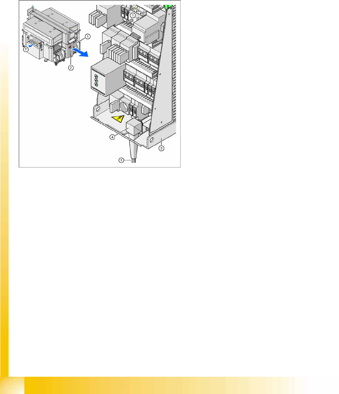
3.2.1 Power supply
The main power supply unit is mounted on a compact rack unit and is located on the left in the middle
section of the machine. From outside, you can only see the red main switch.
A lockable door prevents access to the power supply.
3.2.1.1 Overview of Voltages in the Power Supply Unit
3-9: Power supply
Legend
1. Main switch
2. Cover on the power supply unit
3. Power supply unit
4. Bracket for the cable fixture
5. Mains connection cable
T = PCB transport direction
Overview
Pneumatic Unit Overview of Components
Student Guide (FSE) SIPLACE X Series and X4I
Edition 01/2009 EN Overview
59
3.2.2 Pneumatic Unit
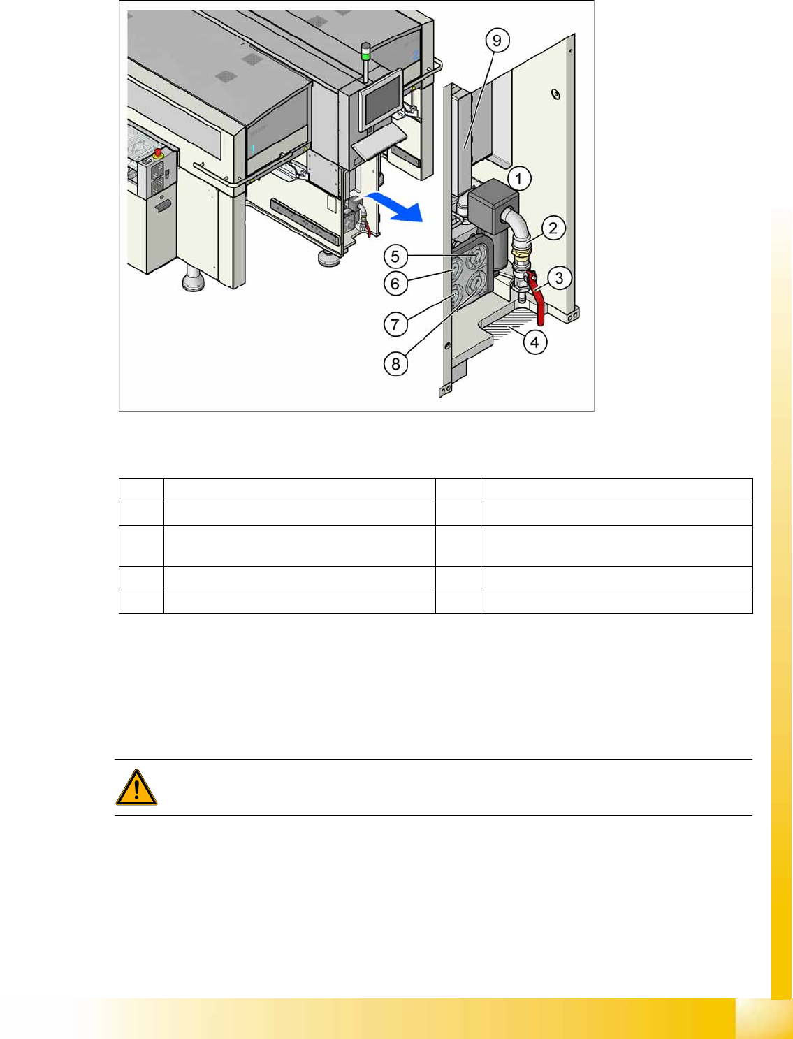
3-10: Pneumatic unit as rack unit
Legend
The pneumatic unit is mounted on a compact rack unit and is located on the right in the middle section
of the machine. Unauthorized access to the unit is prevented by a locked door, which can be opened
with a machine key. The pneumatic unit includes all electrical connections for control/regulation of the
compressed air supply and the conveyor control. The conveyor control with the SMEMA (Siemens)
board interface is responsible for the transport of boards in the machine and for the transport from the
upstream and downstream station.
1 Pneumatic Unit 6 Manometer for bulkcase or nozzle changer DLM
2 Compressed air hose coupling 7 Manometer for gantries
3 Shutoff valve 8 Manometer for machine components (docking
unit, conveyor, cutter, NC C&P20)
4 Gap for compressed air hose 9 Conveyor control TSP301
5 Manometer for input pressure
WARNING:
NEVER disconnect compressed air lines while they are still pressurized. Risk of injury!