00196044-05 - sg x und x4i fse_en.pdf - 第589页
MTC2 Adjustments feed axes MTC2 Calibration and Settings S tudent Guide (FSE) SIPL ACE X Series and X4I Edition 01/2009 EN MTC2 593 14.3.4.3 Light barriers 14-55: Light barriers on the feed axes Legend T ools and Equipme…
MTC2
MTC2 Calibration and Settings Adjustments feed axes
Student Guide (FSE) SIPLACE X Series and X4I
MTC2 Edition 01/2009 EN
592
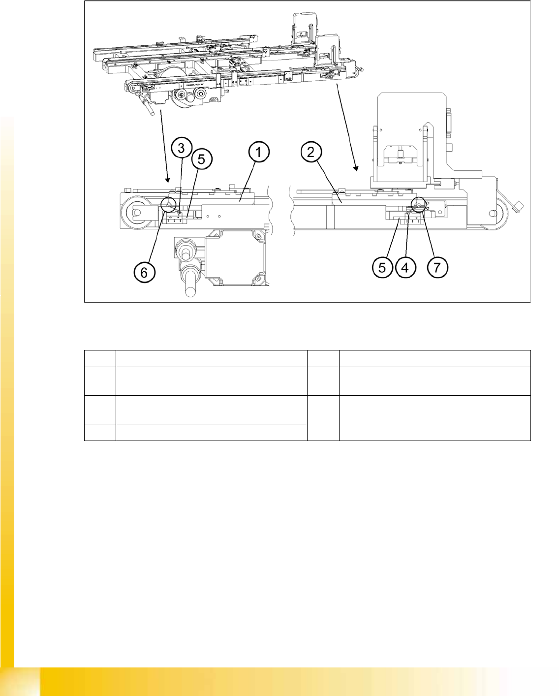
X Set the minimum position of the limit switch above its limit switch holder until there is a distance of
approximately 1 mm between the driver in the zero position and the contact roller of the limit switch
(approximately 10 mm on tower 2).
X Check the feed axis end positions --> „Check and calibrate the travel range end positions".
14-54: Setting the maximum and minimum positions of the limit switches (shown here for tower 1)
Legend
1 Driver at the transfer position 5 Limit switch holder
2 Driver at the zero position 6 Contact area driver/limit switch at maximum
position
3 Limit switch maximum position with contact
roller
7 Contact area driver/limit switch at minimum
position
4 Limit switch minimum position with contact roller
MTC2
Adjustments feed axes MTC2 Calibration and Settings
Student Guide (FSE) SIPLACE X Series and X4I
Edition 01/2009 EN MTC2
593
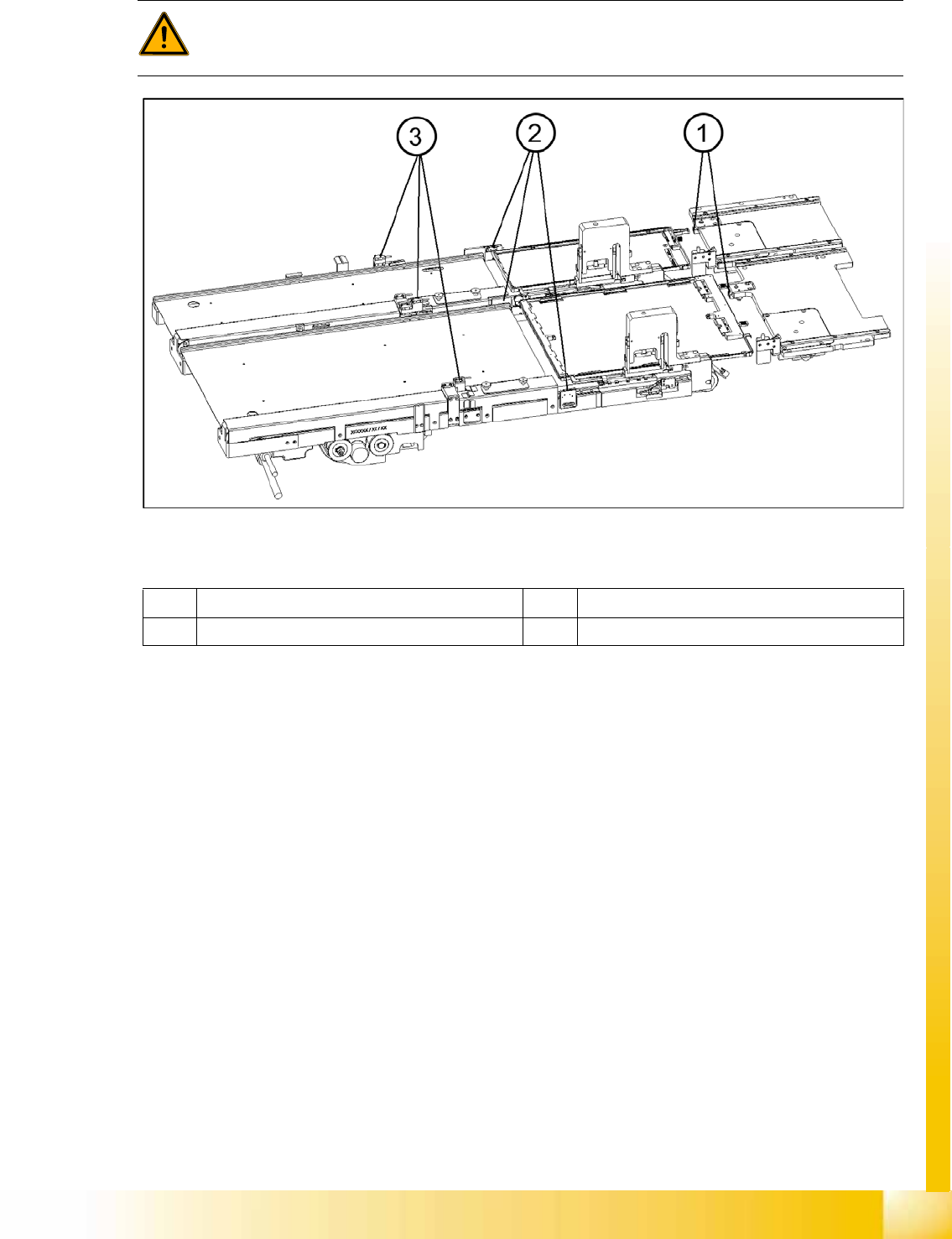
14.3.4.3 Light barriers
14-55: Light barriers on the feed axes
Legend
Tools and Equipment
Adjustment gauge, crash light barriers (03021679-01)
1 set of Allen keys
Preparations
X Move the feed axis into the zero position --> „Check the zero point“.
WARNING:
You may only check and calibrate the light barriers of the feed axis with the correct zero
positions, transfer positions and removal positions of the lifting and feed axes.
1 Handle sensor 3 Crash light barriers
2 WTC safety query
MTC2
MTC2 Calibration and Settings Adjustments feed axes
Student Guide (FSE) SIPLACE X Series and X4I
MTC2 Edition 01/2009 EN
594
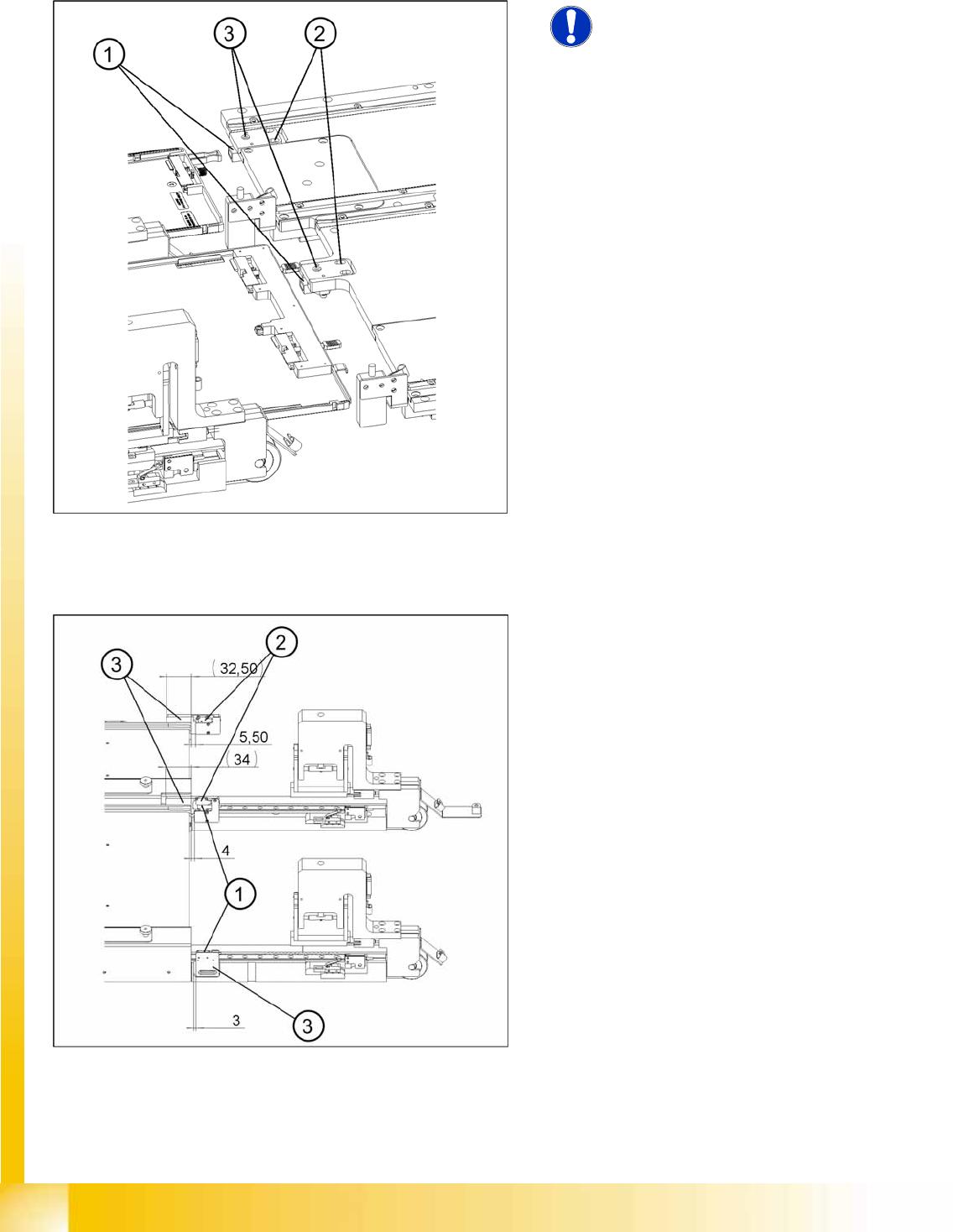
Checking and setting the handle sensors
Checking and setting the WTC safety query
14-56: Checking and setting the handle sensors
NOTE:
The handle sensors each comprise a
reflecting light barrier which can detect
the handle of the WTC or the side of the
handle of the WTC XL. An LED
indicates the switching status of the
sensor.
Legend
1. Reflecting light barriers of the handle sensors
2. Mounting plates with clamping screws
3. LEDs
X Unscrew the clamping screws of the mounting
plate.
X Move the mounting plate in the direction of the
WTC until the reflecting light barrier responds
(the LED will change its status). Fix the plate in
place there.
X Ensure that the status of the LED remains the
same when you move the locked WTC. If
necessary, move the mounting plate a little
further in the direction of the WTC.
X Firmly tighten the clamping screws.
14-57: Checking and setting the WTC safety queries
Legend
1. Light barrier for the WTC safety query for
tower 1
2. Light barrier for the WTC safety query for
tower 2
3. Light barrier holder with clamping screws