00196044-05 - sg x und x4i fse_en.pdf - 第593页
MTC2 Adjustments feed axes MTC2 Calibration and Settings S tudent Guide (FSE) SIPL ACE X Series and X4I Edition 01/2009 EN MTC2 597 14.3.4.4 Disengaging mechanism T ools and Equipment 1 set of Allen keys Prep arations …
MTC2
MTC2 Calibration and Settings Adjustments feed axes
Student Guide (FSE) SIPLACE X Series and X4I
MTC2 Edition 01/2009 EN
596
X Unscrew the clamping screws of the holder for tower 1 and the middle holder (base section) and
place the bottom light barrier pair onto the middle of the gauge. Ensure that the holders do not jam
in their guide.
X Firmly tighten the clamping screws. Ensure that the holders cannot be moved or turned any more.
X At this setting, the bottom light barrier pair should still just shine through at a height of
12.35 mm + 0.05 mm and no longer shine through at a height of 12.45 mm + 0.05 mm. (dimensions
in diagram)
X On the adjustment gauge the light barrier should still shine through at a height of 9,75 mm and at a
height of 9,85 mm the light should be interrupted.
X Place the adjustment gauge for the crash light barriers across the rail of the feed axis for tower 2.
X Unscrew the clamping screws of the holder for tower 2 and the middle holder (movable section) and
place the bottom light barrier pair onto the middle of the gauge. Ensure that the holders do not jam
in their guide.
X Firmly tighten the clamping screws. Ensure that the holders cannot be moved or turned any more.
X At this setting, the bottom light barrier pair should still just shine through at a height of
11.40 mm + 0.05 mm and no longer shine through at a height of 11.50 mm + 0.05 mm.
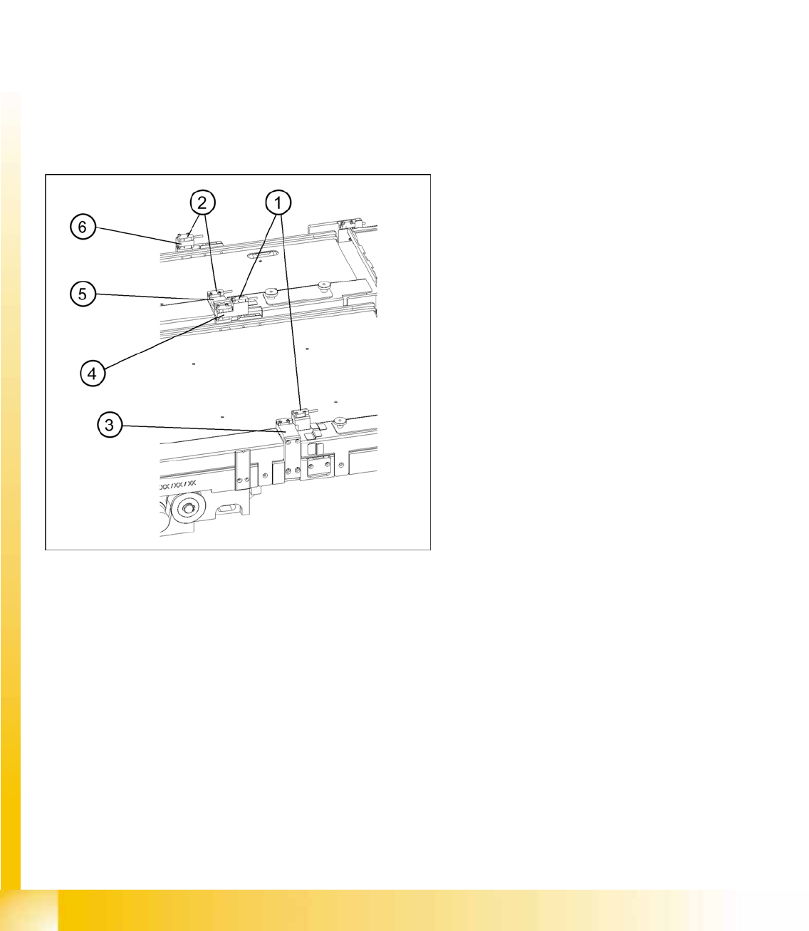
14-58: Checking and Setting the Crash Light Barriers
Legend
1. Crash light barriers for tower 1
2. Crash light barriers for tower 2
3. Light barrier holder for tower 1 with clamping
screws
4. Middle light barrier holder with clamping
screws, base section
5. Middle light barrier holder with clamping
screws, movable section
6. Light barrier holder for tower 2 with clamping
screws
MTC2
Adjustments feed axes MTC2 Calibration and Settings
Student Guide (FSE) SIPLACE X Series and X4I
Edition 01/2009 EN MTC2
597
14.3.4.4 Disengaging mechanism
Tools and Equipment
1 set of Allen keys
Preparations
X Empty the MTC2 completely (see the User Manual).
X Move the feeder axis to the zero position (see Section (14.3.2.2 Feed axis
J
575 ) ) and engage
the driver into the WTC.
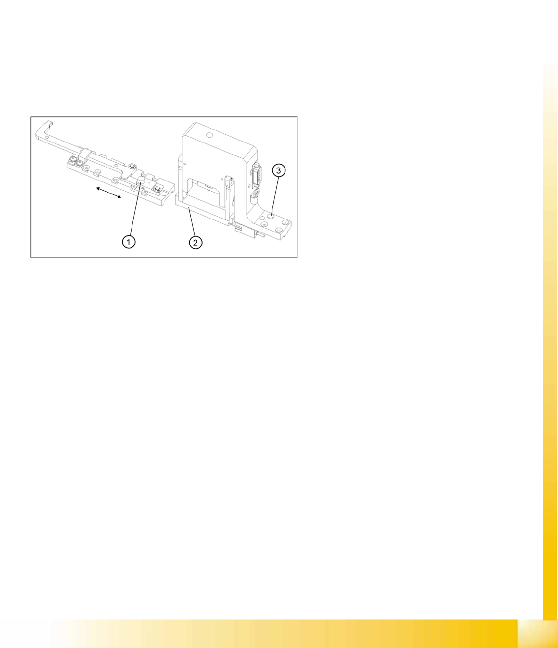
Setting the disengaging mechanism
X Move the driver over the belt until it lies outside the disengaging mechanism.
X Check that the driver in its dead center position engages centrally with the disengaging aperture
when it is moved back.
X When the guide roller is pushed through the middle of the aperture, set the position of the aperture
with the 4 securing screws of the disengaging mechanism.
14-59: Setting the disengaging mechanism
Legend
1. Driver guide roller in dead center position
2. Disengaging mechanism aperture
3. Disengaging mechanism securing screws
MTC2
MTC2 Calibration and Settings Converting the power supply
Student Guide (FSE) SIPLACE X Series and X4I
MTC2 Edition 01/2009 EN
598
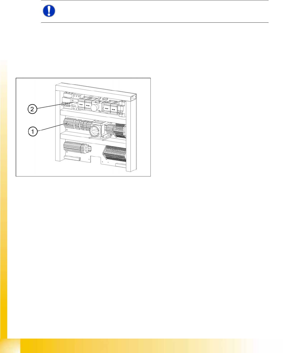
14.3.5 Converting the power supply
To operate the MTC2 in the USA or in Japan, the power supply needs to be changed from 400 V, 50 Hz
to 208/204 V, 50/60 Hz.
14.3.5.1 Tools and Equipment
1 set of screwdrivers
3 additional bridges
14.3.5.2 Procedure
NOTE:
To convert the power supply from 208/204 V to 400 V, the same procedure must be carried out
in the reverse order.
14-60: Electronics board
Legend
1. Bridges on the voltage distributor terminal X01
2. Motor Circuit Breaker