00196044-05 - sg x und x4i fse_en.pdf - 第60页
Overview Overview of Components Pne umatic Unit S tudent Guide (FSE) SI PL ACE X Series and X4I Overview Edition 01/2009 EN 60 3.2.2.1 Pneumatic Circuit For Cooling the Y Linea r Motors in Placement Areas 1/2 An addition…
Overview
Pneumatic Unit Overview of Components
Student Guide (FSE) SIPLACE X Series and X4I
Edition 01/2009 EN Overview
59
3.2.2 Pneumatic Unit
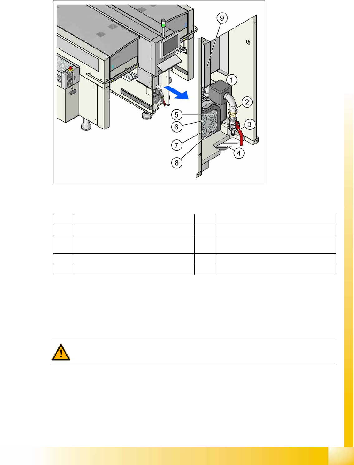
3-10: Pneumatic unit as rack unit
Legend
The pneumatic unit is mounted on a compact rack unit and is located on the right in the middle section
of the machine. Unauthorized access to the unit is prevented by a locked door, which can be opened
with a machine key. The pneumatic unit includes all electrical connections for control/regulation of the
compressed air supply and the conveyor control. The conveyor control with the SMEMA (Siemens)
board interface is responsible for the transport of boards in the machine and for the transport from the
upstream and downstream station.
1 Pneumatic Unit 6 Manometer for bulkcase or nozzle changer DLM
2 Compressed air hose coupling 7 Manometer for gantries
3 Shutoff valve 8 Manometer for machine components (docking
unit, conveyor, cutter, NC C&P20)
4 Gap for compressed air hose 9 Conveyor control TSP301
5 Manometer for input pressure
WARNING:
NEVER disconnect compressed air lines while they are still pressurized. Risk of injury!

Overview
Overview of Components Pneumatic Unit
Student Guide (FSE) SIPLACE X Series and X4I
Overview Edition 01/2009 EN
60
3.2.2.1 Pneumatic Circuit For Cooling the Y Linear Motors in Placement Areas 1/2
An additional pneumatic circuit, supplied with ambient air, has been integrated to cool the Y linear
motors. The ambient air is sucked in via a filter, with the help of a fan motor and is distributed to the Y
motors. The compressed air then escapes through the sides of the Y motors.
3.2.2.2 Pneumatic Circuit For Cooling the X Linear Motors in Placement Areas 1/2
The X motors are cooled by the discharged air from the vacuum generator of the C&P20A head.
3.2.2.3 Compressed Air Distributor Block
The pneumatic unit is used to prepare and distribute the compressed air required in the machine. The
inlet pressure at the compressed air connection must be at least 5.0 bar.
The following pneumatic circuits are supplied with compressed air via the distributor block:
Gantries 1 - 4 (placement heads), vacuum generation: 5.0 bar
Conveyor system: 5.0 bar
Tape cutter for locations 1 - 4: 5.0 bar
Nozzle changer for locations 1 - 4: 5.0 bar
Feed-in units for the changeover tables: 5.0 bar
Bulkcase feeder for locations 1 - 4: 2.5 bar
Fine adjustment for the individual pneumatic circuits is performed directly at the pneumatic units, via the
adjustment valves.
Overview
Sectors 1 - 4 Overview of Components
Student Guide (FSE) SIPLACE X Series and X4I
Edition 01/2009 EN Overview
61
3.2.3 Sectors 1 - 4
Sector 1/3:
Connector module for the safety circuit and the Start/Stop button
Boards for single-handed operation of changeover tables for location 1/4 or sector 3 for locations 3/2.
Signaling circuit for the hoods
Sector 2 (main distributor):
CAN I/O module with the 1 wire module (1 wire is only used for the temperature sensors.)
DC distributor for illumination of cameras in placement area 2
Main distributor (connector module)
Terminals X1qa (GND, +5 V, +15 V, -15 V, +24 V, Start/Stop signal, covers, emergency STOP
signal, SW release signal)
Connector module for the safety circuit and Start/Stop button
Sector 4 (subdistributor):
CAN I/O module with the 1 wire module (1 wire is only used for the temperature sensors.)
DC distributor for illumination of cameras in placement area 1
Intermediate distributor (connector module)
Terminals X1ra (GND, +5 V, +15 V, -15 V, +24 V, Start/Stop signal, covers, emergency STOP
signal, ...)
Connector module for the safety circuit and Start/Stop button
Relay and fuse for the hood fans (24 V)
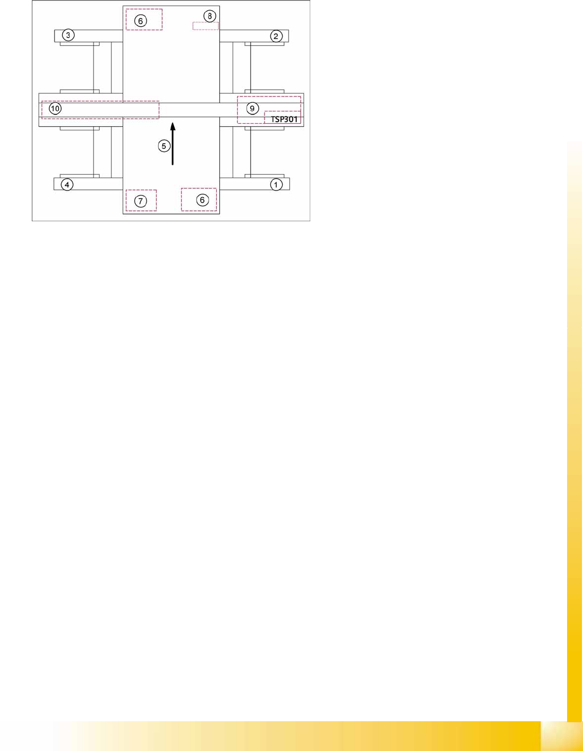
3-11: Overview of sectors 1 - 4
Legend
1. Sector 1
2. Sector 2
3. Sector 3
4. Sector 4
5. Transport direction
6. Axis unit 1/2
7. Computer unit
8. DC/DC converter FCU (feeder control unit)
9. Pneumatic unit with conveyor control
10. Power supply unit