00196044-05 - sg x und x4i fse_en.pdf - 第61页
Overview Sectors 1 - 4 Overview of Components S tudent Guide (FSE) SIPL ACE X Series and X4I Edition 01/2009 EN Overview 61 3.2.3 Sectors 1 - 4 Sector 1/3: Connector module for the safety circuit and the Start/Stop but…

Overview
Overview of Components Pneumatic Unit
Student Guide (FSE) SIPLACE X Series and X4I
Overview Edition 01/2009 EN
60
3.2.2.1 Pneumatic Circuit For Cooling the Y Linear Motors in Placement Areas 1/2
An additional pneumatic circuit, supplied with ambient air, has been integrated to cool the Y linear
motors. The ambient air is sucked in via a filter, with the help of a fan motor and is distributed to the Y
motors. The compressed air then escapes through the sides of the Y motors.
3.2.2.2 Pneumatic Circuit For Cooling the X Linear Motors in Placement Areas 1/2
The X motors are cooled by the discharged air from the vacuum generator of the C&P20A head.
3.2.2.3 Compressed Air Distributor Block
The pneumatic unit is used to prepare and distribute the compressed air required in the machine. The
inlet pressure at the compressed air connection must be at least 5.0 bar.
The following pneumatic circuits are supplied with compressed air via the distributor block:
Gantries 1 - 4 (placement heads), vacuum generation: 5.0 bar
Conveyor system: 5.0 bar
Tape cutter for locations 1 - 4: 5.0 bar
Nozzle changer for locations 1 - 4: 5.0 bar
Feed-in units for the changeover tables: 5.0 bar
Bulkcase feeder for locations 1 - 4: 2.5 bar
Fine adjustment for the individual pneumatic circuits is performed directly at the pneumatic units, via the
adjustment valves.
Overview
Sectors 1 - 4 Overview of Components
Student Guide (FSE) SIPLACE X Series and X4I
Edition 01/2009 EN Overview
61
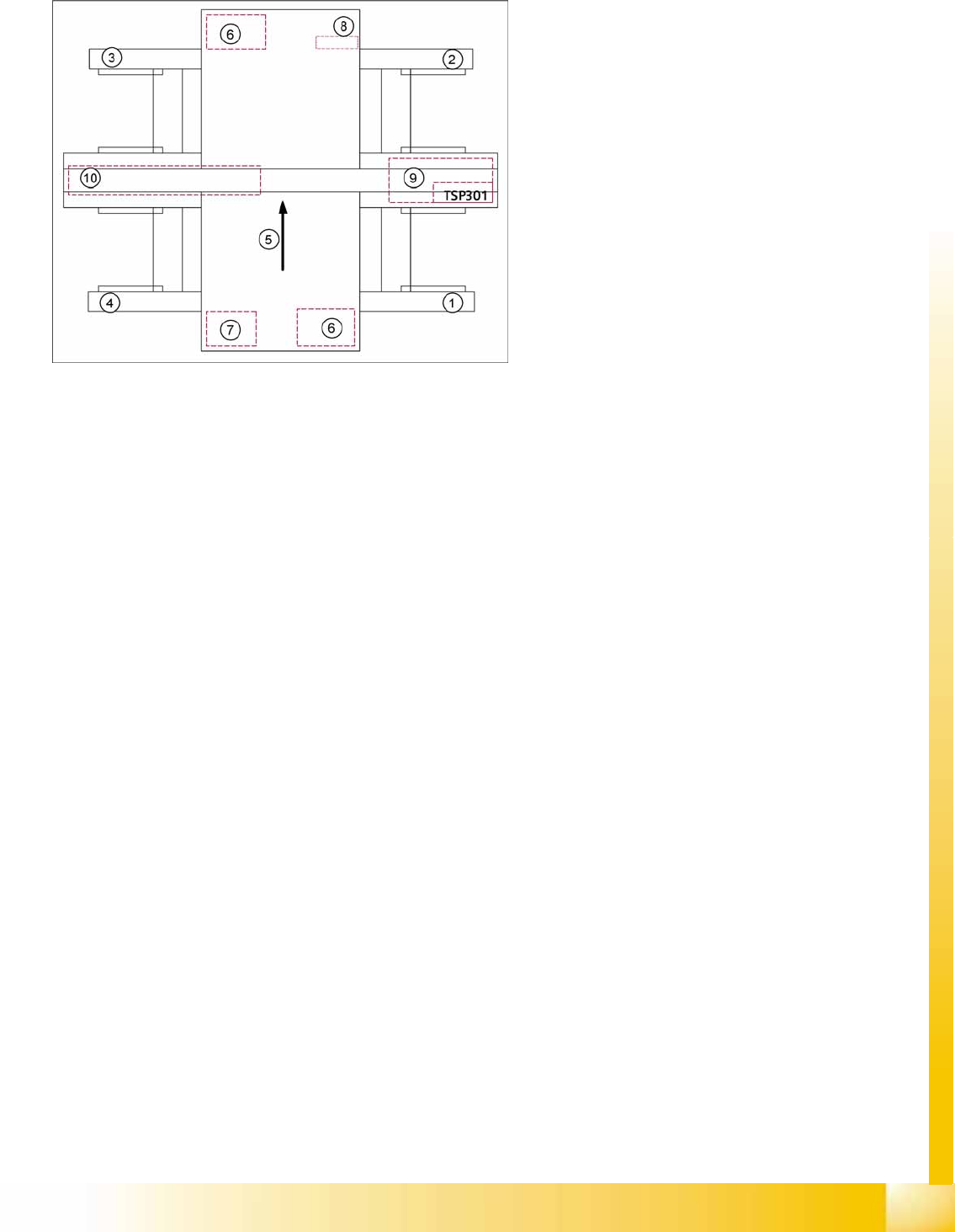
3.2.3 Sectors 1 - 4
Sector 1/3:
Connector module for the safety circuit and the Start/Stop button
Boards for single-handed operation of changeover tables for location 1/4 or sector 3 for locations 3/2.
Signaling circuit for the hoods
Sector 2 (main distributor):
CAN I/O module with the 1 wire module (1 wire is only used for the temperature sensors.)
DC distributor for illumination of cameras in placement area 2
Main distributor (connector module)
Terminals X1qa (GND, +5 V, +15 V, -15 V, +24 V, Start/Stop signal, covers, emergency STOP
signal, SW release signal)
Connector module for the safety circuit and Start/Stop button
Sector 4 (subdistributor):
CAN I/O module with the 1 wire module (1 wire is only used for the temperature sensors.)
DC distributor for illumination of cameras in placement area 1
Intermediate distributor (connector module)
Terminals X1ra (GND, +5 V, +15 V, -15 V, +24 V, Start/Stop signal, covers, emergency STOP
signal, ...)
Connector module for the safety circuit and Start/Stop button
Relay and fuse for the hood fans (24 V)
3-11: Overview of sectors 1 - 4
Legend
1. Sector 1
2. Sector 2
3. Sector 3
4. Sector 4
5. Transport direction
6. Axis unit 1/2
7. Computer unit
8. DC/DC converter FCU (feeder control unit)
9. Pneumatic unit with conveyor control
10. Power supply unit
Overview
Overview of Components Computer Unit with BoxPC
Student Guide (FSE) SIPLACE X Series and X4I
Overview Edition 01/2009 EN
62
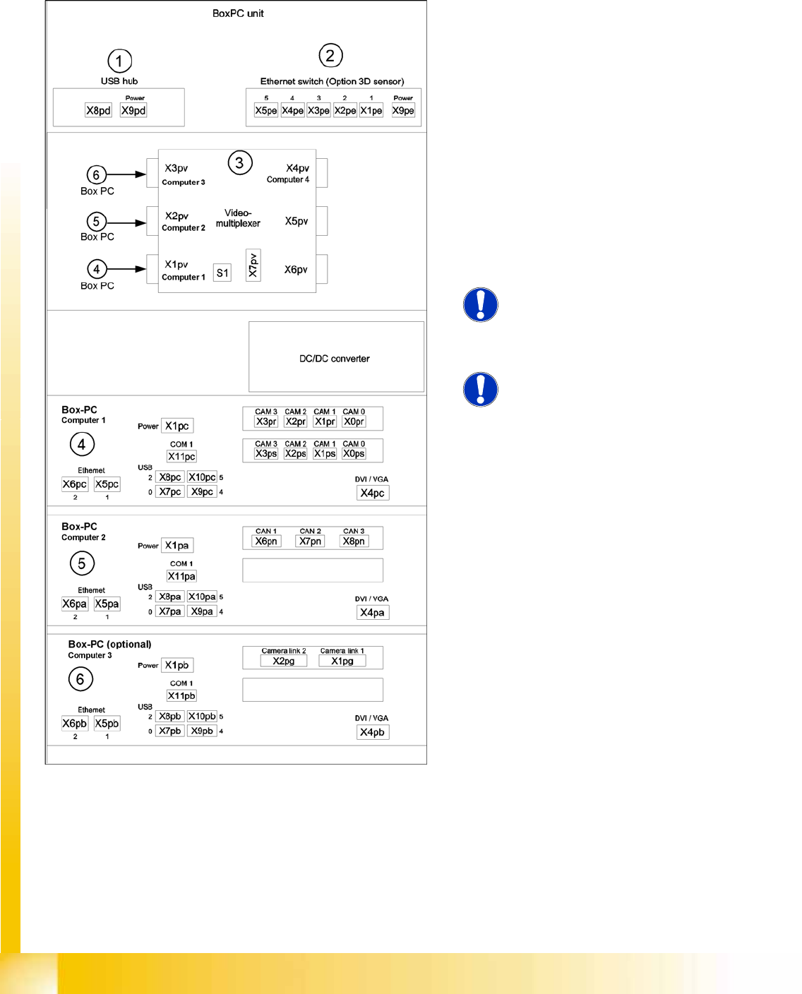
3.2.4 Computer Unit with BoxPC
In placement machines from X-series MA. No. 600 and X4I have BoxPCs in the computer unit.
Up to 3 BoxPCs will be installed, depending on the machine type and configuration.
3-12: Computer unit with BoxPC [00351894-xx]
Position of assemblies in the computer
unit
1. 4 port USB hub 2.0
2. Ethernet switch (only for optional 3D sensor)
3. Video multiplexer
4. Computer 1:
Vision computer (from SW 70x)
5. Computer 2:
Station computer (from SW 70x)
6. Computer 3:
Additional BoxPC – only for 3d sensor option
NOTE:
An external DVD drive is supplied with
the delivery package.
NOTE:
In future, X series machines will be
supplied with higher performance
BoxPCs. This means that machine
control and the Vision function are
handled by only one BoxPC.