00196044-05 - sg x und x4i fse_en.pdf - 第66页
Overview Overview of Components Changeover Table Components S tudent Guide (FSE) SI PL ACE X Series and X4I Overview Edition 01/2009 EN 66 3.2.6.2 Setting the Height of the Ch angeover T able The change over table can be…
Overview
Changeover Table Components Overview of Components
Student Guide (FSE) SIPLACE X Series and X4I
Edition 01/2009 EN Overview
65
3.2.6 Changeover Table Components
SIPLACE X machines with SW70x only support the new generation of X feeders and X component
changeover tables. This changeover table does not have any electronic assemblies, such as the
communication unit for feeder supply and control in the previous tables. The power supply for the feeders
is without contact, via an inductive interface on the docking unit, directly to the feeders. Control and
communication between the feeder control unit (FCU) and the feeders is provided via two optoelectronic
channels (light conductors). The FCU is connected to the computer unit in the machine via the machine
CAN Bus. Only X tables can be used on the machines.
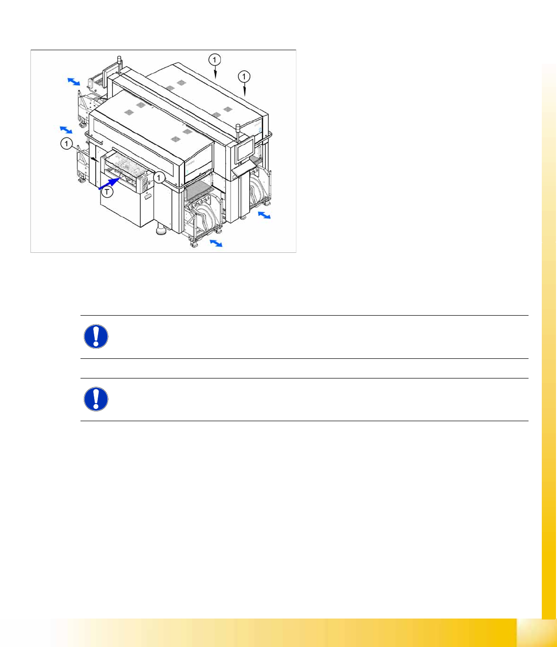
3.2.6.1 Docking and Undocking
Each X feeder table has 40 slots for 8 mm X feeders, giving a total capacity of 160 individual tracks on
4 changeover tables.
3-14: Shows the button for docking and undocking changeover tables
Legend
1. Button for docking and undocking changeover
tables
T = transport direction
The changeover table is automatically docked at
the machine, with two pneumatic cylinders. For
docking, the changeover table is moved up to the
docking unit, the hood is closed and the button is
pressed. For undocking, the cover is opened and
the button is pressed again.
NOTE: From software 70x
X machines from software 70x only support X tables.
NOTE: X4I
Due to the rotated gantries, there are only 34 tracks available at locations 2 and 4 of the X4I.
Overview
Overview of Components Changeover Table Components
Student Guide (FSE) SIPLACE X Series and X4I
Overview Edition 01/2009 EN
66
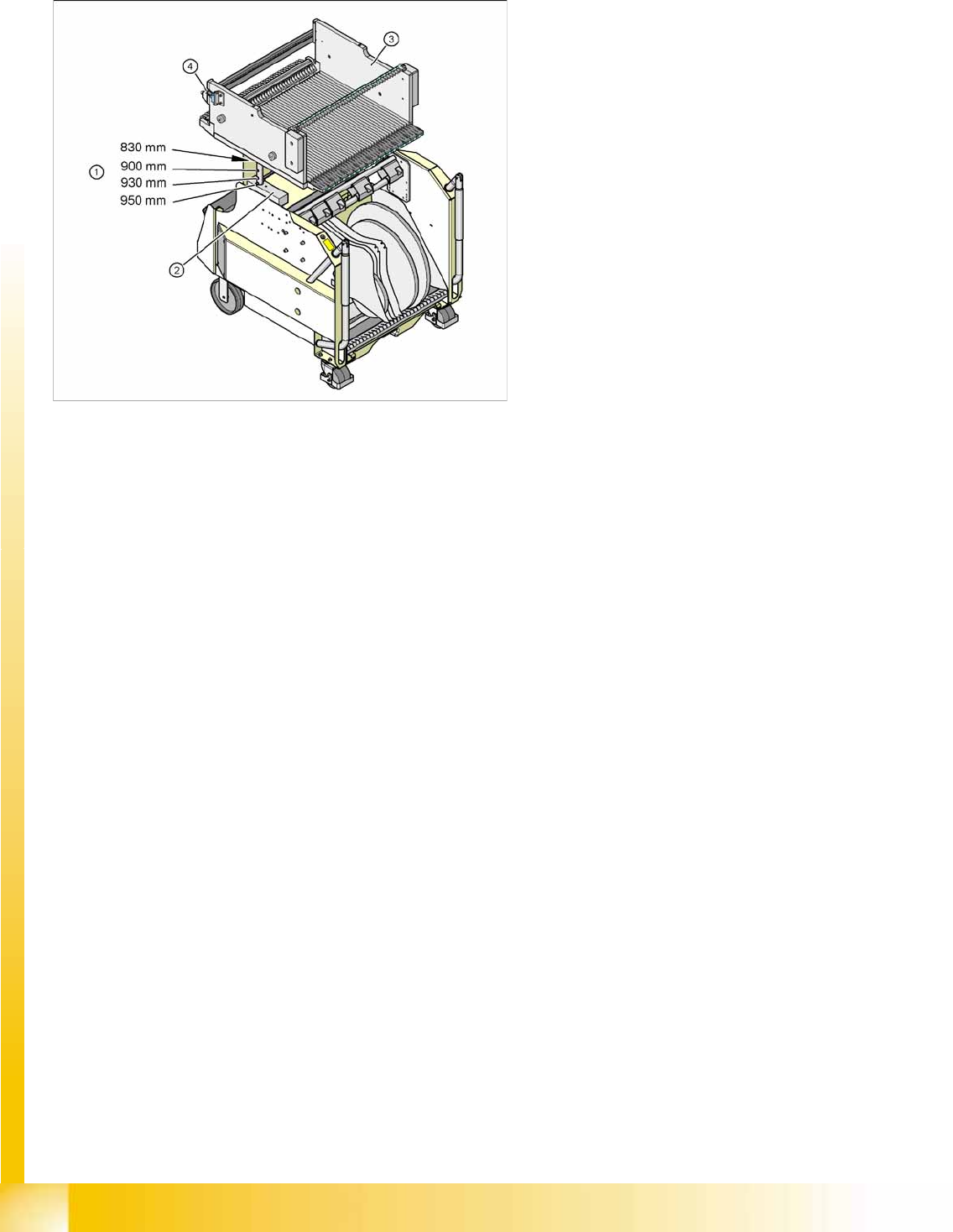
3.2.6.2 Setting the Height of the Changeover Table
The changeover table can be manually set to the following PCB conveyor heights
830 mm ±15 mm standard height
900 mm ±15 mm SMEMA height
930 mm ±15 mm SMEMA height
950 mm ±15 mm SMEMA height
3-15: Component table for X feeder
Legend
1. Drillings for the various PCB conveyor heights,
adjustment via insertion of a spring pin.
2. Contact surface (block) for the upper part of
the table
3. Changeover table
4. Reed switch for closing the safety circuit to the
docking unit
Overview
Changeover Table Components Overview of Components
Student Guide (FSE) SIPLACE X Series and X4I
Edition 01/2009 EN Overview
67
3.2.6.3 Overview of X Feeders
X Feeder Operator Panel
3-16: Example 8 mm X feeder
Legend
1. Pickup position
2. Motors for moving components
3. Motor for cover foil
4. Display, operating panel and status display
5. Mechanical and electrical unlocking function
The new generation of X feeders enables you to
set up a separate feeder for each component used
at the machines (single track feeders). This
ensures optimum use of the machine locations
and optimum configuration of the setups in the
placement process.
The X feeders can be logged off should errors
occur during production and can then be replaced
by other feeders, which are logged back into the
production run.
As an option, a splice sensor can be directly
integrated into the feeder.
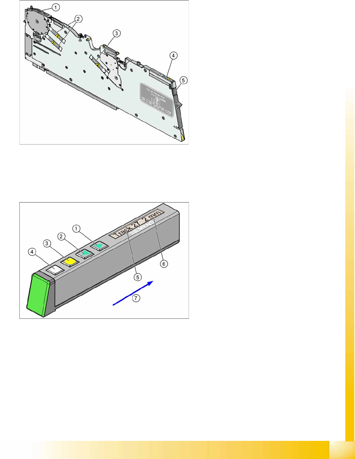
3-17: X Feeder Operator Panel
Legend
1. "Forwards" button
Press briefly to move the tape by the set cycle
step.
Press for longer to move the tape forwards.
Make sure the cover foil is not clamped in.
2. "Backwards" button
Press briefly and release slowly to move the
tape backwards by the set cycle step
Prolonged pressing moves the tape back.
(Both functions should only be performed
without the cover foil fitted).
3. Press the "Foil" button to start the foil drive
motor. This runs until the foil has been
stretched tight and the motor toggle switch
turns off or until the timer has counted 30
seconds.
4. Briefly press the "SET" button to switch over to
the next menu on the main menu level. Press
for longer to request component verification.
5. Display showing track on location
6. Cycle step
7. Transport direction