00196044-05 - sg x und x4i fse_en.pdf - 第68页
Overview Overview of Components X/Y Axis Construction S tudent Guide (FSE) SI PL ACE X Series and X4I Overview Edition 01/2009 EN 68 3.2.7 X/Y Axis Con struction 3.2.7.1 X Axis Construction 3-18: X Axis Construction Lege…
Overview
Changeover Table Components Overview of Components
Student Guide (FSE) SIPLACE X Series and X4I
Edition 01/2009 EN Overview
67
3.2.6.3 Overview of X Feeders
X Feeder Operator Panel
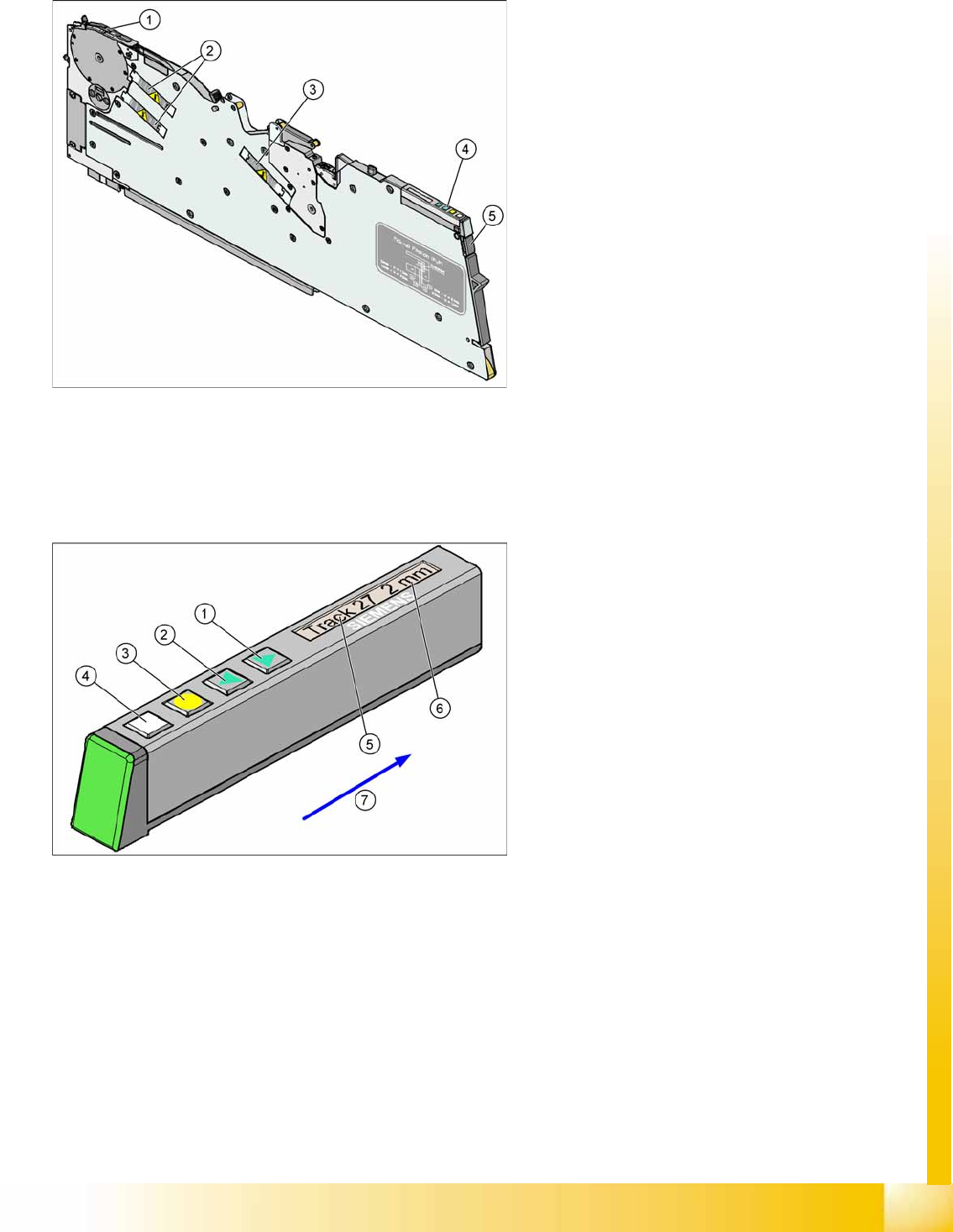
3-16: Example 8 mm X feeder
Legend
1. Pickup position
2. Motors for moving components
3. Motor for cover foil
4. Display, operating panel and status display
5. Mechanical and electrical unlocking function
The new generation of X feeders enables you to
set up a separate feeder for each component used
at the machines (single track feeders). This
ensures optimum use of the machine locations
and optimum configuration of the setups in the
placement process.
The X feeders can be logged off should errors
occur during production and can then be replaced
by other feeders, which are logged back into the
production run.
As an option, a splice sensor can be directly
integrated into the feeder.
3-17: X Feeder Operator Panel
Legend
1. "Forwards" button
Press briefly to move the tape by the set cycle
step.
Press for longer to move the tape forwards.
Make sure the cover foil is not clamped in.
2. "Backwards" button
Press briefly and release slowly to move the
tape backwards by the set cycle step
Prolonged pressing moves the tape back.
(Both functions should only be performed
without the cover foil fitted).
3. Press the "Foil" button to start the foil drive
motor. This runs until the foil has been
stretched tight and the motor toggle switch
turns off or until the timer has counted 30
seconds.
4. Briefly press the "SET" button to switch over to
the next menu on the main menu level. Press
for longer to request component verification.
5. Display showing track on location
6. Cycle step
7. Transport direction
Overview
Overview of Components X/Y Axis Construction
Student Guide (FSE) SIPLACE X Series and X4I
Overview Edition 01/2009 EN
68
3.2.7 X/Y Axis Construction
3.2.7.1 X Axis Construction
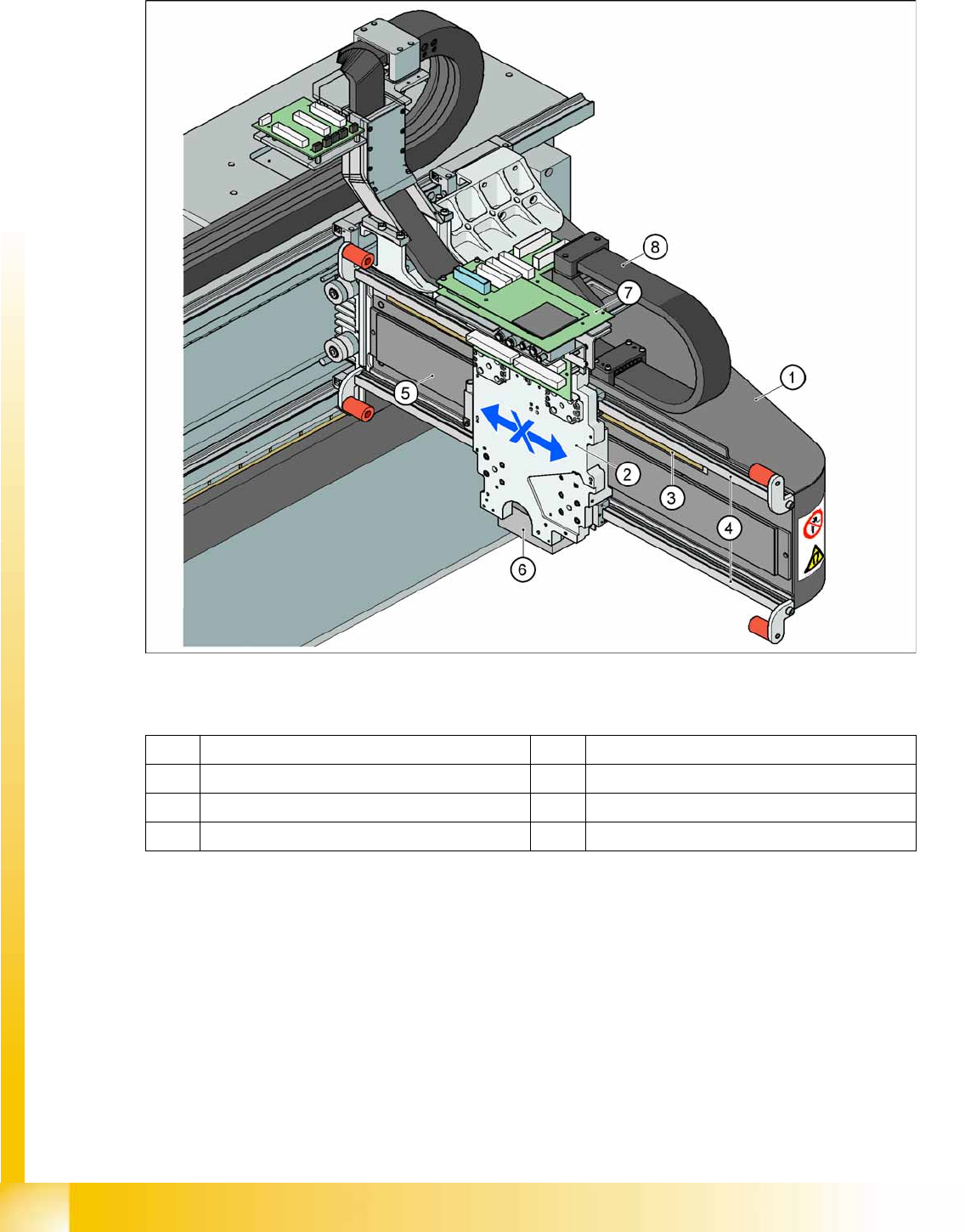
3-18: X Axis Construction
Legend – main X axis modules
The following modules are installed on the head mount (2):
PCB camera (6)
Head board with Vision board (7) (head interface, head adapter)
Incremental encoder
C&P20A head, CPP head or Twin Head
The gantry arm (1) is made of carbon fiber. This gives the gantry arm high torsional rigidity with minimum
weight. The X axis is driven by a linear motor. The secondary part of the drive consists of a permanent
magnet and is fixed to the gantry arm, while the primary part is screwed to the head mounting plate.
1 Gantry X (frame) 5 Linear drive permanent magnet (secondary)
2 Fixture plate with head X linear motor (primary) 6 PCB camera mount
3 Linear incremental encoder 7 Head interface board
4 Linear guide rails X axis 8 X trailing cable
Overview
X/Y Axis Construction Overview of Components
Student Guide (FSE) SIPLACE X Series and X4I
Edition 01/2009 EN Overview
69
3.2.7.2 X Axis Technical Data
3.2.7.3 Y Axis Construction
3.2.7.4 Y Axis Technical Data
Drive Direct, linear drive
Maximum speed 2.5 m/sec.
Travel range 471 mm
Mechanical travel range 480 mm
Measuring system Linear incremental encoder
Length of linear incremental encoder 520 mm
Resolution 1 µm
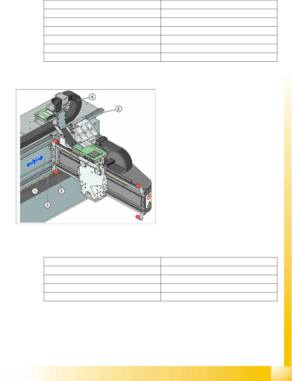
3-19: Y Axis Construction
Legend – main Y axis modules
1. Linear drive permanent magnet (secondary)
2. Linear guide rails
3. Linear incremental encoder
4. Trailing cable
5. Linear motor (primary)
The Y axis is driven by a linear motor. The
secondary part of the drive consists of a
permanent magnet and is fixed to the machine
frame. The primary part is screwed to the gantry
arm.
Drive Direct, linear drive
Maximum speed 2.5 m/sec.
Gantry travel range 1430 mm
Length of incremental encoder 1850 mm
Resolution 1 µm