00196044-05 - sg x und x4i fse_en.pdf - 第69页
Overview X/Y Axis Construction Overview of Components S tudent Guide (FSE) SIPL ACE X Series and X4I Edition 01/2009 EN Overview 69 3.2.7.2 X Axis T echnical Dat a 3.2.7.3 Y Axis Construction 3.2.7.4 Y Axis T echnical Da…
Overview
Overview of Components X/Y Axis Construction
Student Guide (FSE) SIPLACE X Series and X4I
Overview Edition 01/2009 EN
68
3.2.7 X/Y Axis Construction
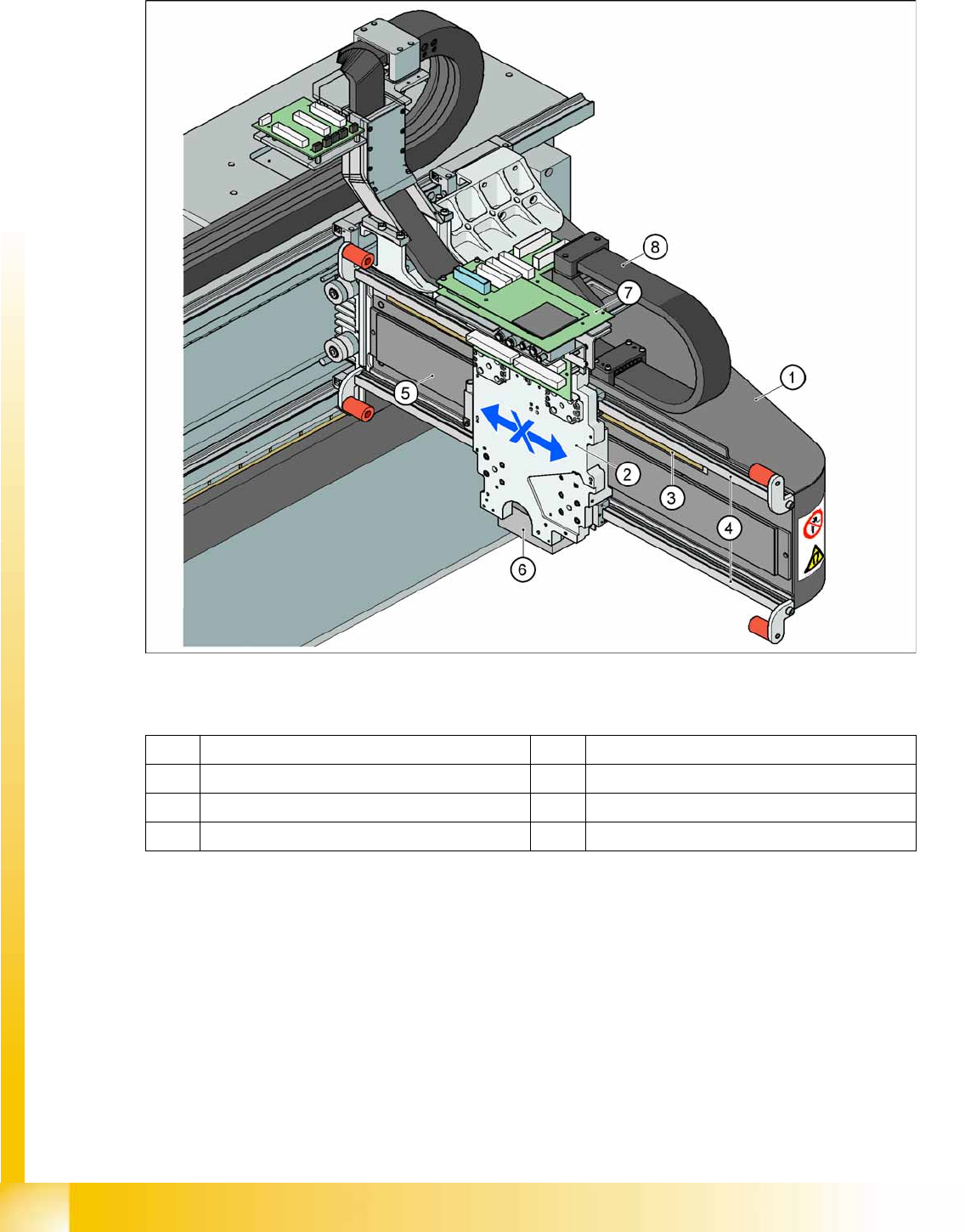
3.2.7.1 X Axis Construction
3-18: X Axis Construction
Legend – main X axis modules
The following modules are installed on the head mount (2):
PCB camera (6)
Head board with Vision board (7) (head interface, head adapter)
Incremental encoder
C&P20A head, CPP head or Twin Head
The gantry arm (1) is made of carbon fiber. This gives the gantry arm high torsional rigidity with minimum
weight. The X axis is driven by a linear motor. The secondary part of the drive consists of a permanent
magnet and is fixed to the gantry arm, while the primary part is screwed to the head mounting plate.
1 Gantry X (frame) 5 Linear drive permanent magnet (secondary)
2 Fixture plate with head X linear motor (primary) 6 PCB camera mount
3 Linear incremental encoder 7 Head interface board
4 Linear guide rails X axis 8 X trailing cable
Overview
X/Y Axis Construction Overview of Components
Student Guide (FSE) SIPLACE X Series and X4I
Edition 01/2009 EN Overview
69
3.2.7.2 X Axis Technical Data
3.2.7.3 Y Axis Construction
3.2.7.4 Y Axis Technical Data
Drive Direct, linear drive
Maximum speed 2.5 m/sec.
Travel range 471 mm
Mechanical travel range 480 mm
Measuring system Linear incremental encoder
Length of linear incremental encoder 520 mm
Resolution 1 µm
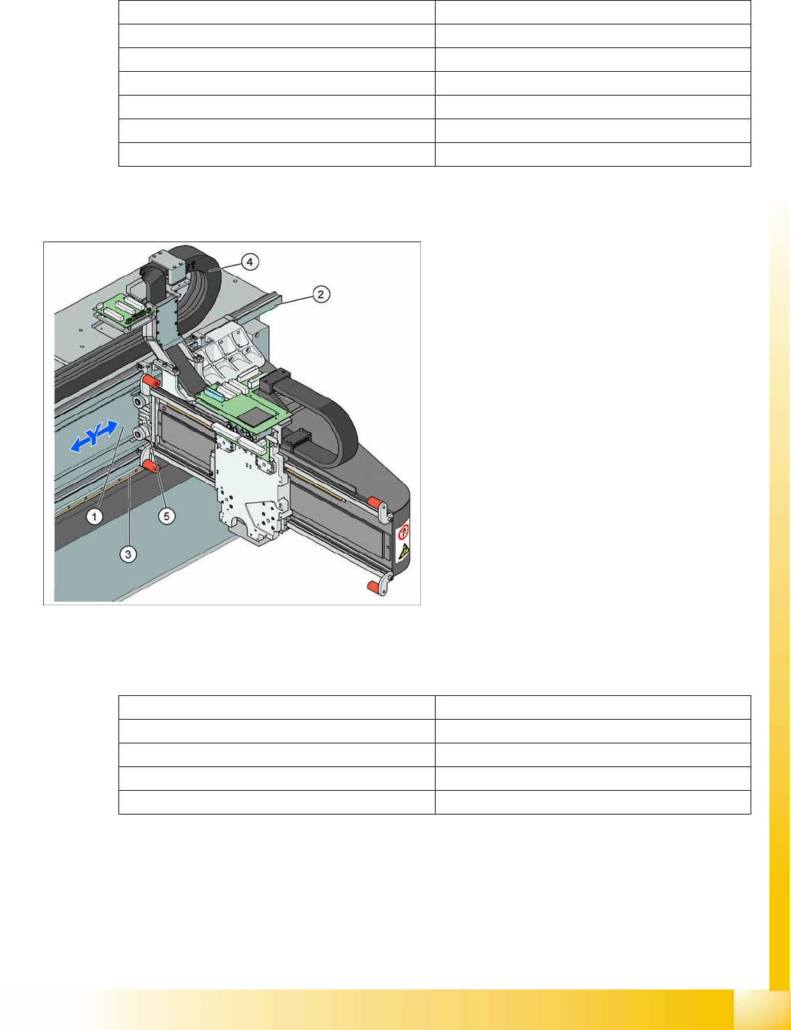
3-19: Y Axis Construction
Legend – main Y axis modules
1. Linear drive permanent magnet (secondary)
2. Linear guide rails
3. Linear incremental encoder
4. Trailing cable
5. Linear motor (primary)
The Y axis is driven by a linear motor. The
secondary part of the drive consists of a
permanent magnet and is fixed to the machine
frame. The primary part is screwed to the gantry
arm.
Drive Direct, linear drive
Maximum speed 2.5 m/sec.
Gantry travel range 1430 mm
Length of incremental encoder 1850 mm
Resolution 1 µm
Overview
Overview of Components SIPLACE Vision
Student Guide (FSE) SIPLACE X Series and X4I
Overview Edition 01/2009 EN
70
3.2.8 SIPLACE Vision
The new digital SIPLACE Vision solution is another step towards the satisfaction of customer demands
for greater speed, flexibility and robustness.
Advantages of the digital Vision system:
Robust and fast computing algorithms
Flexible measurement processes
Self-learning graphical interface
Geometric description of components at the machine
State-of-the-art digital camera hardware
Homogenous illumination of camera field of vision and components
Each C&P head has its own digital component camera. For Twin Heads, a stationary camera is installed
in the machine.
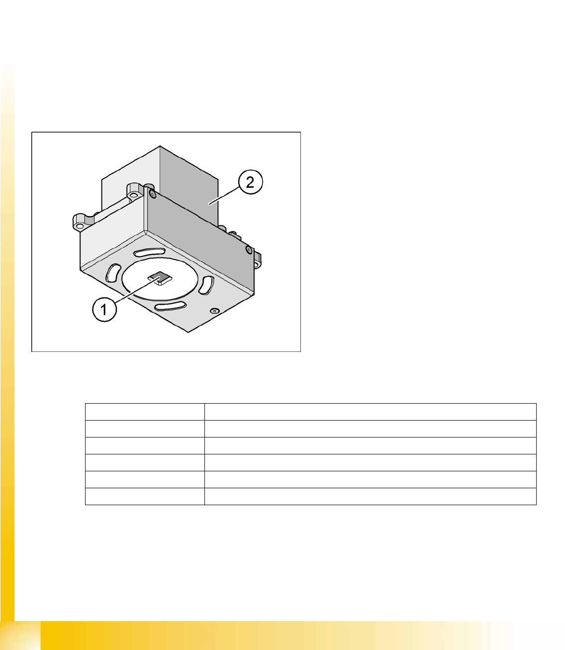
3.2.8.1 Digital PCB Camera (Standard) SST34
Technical Data
3-20: PCB camera under the gantry (X axis)
Legend
1. Camera lens system
2. Camera amplifier
Illumination control for blue and infrared LEDs in
the various illumination levels
PCB fiducials max. 3 per placement program
Field of vision 5.7 mm x 5.7 mm
Type of illumination Front lighting
Resolution 9.8µm/pixels
Fiducial size 0.3 to 2.5 mm (can be up to 3.0 mm, depending on the PCB conveyor tolerance)
Camera type.sst 34.sst