00196044-05 - sg x und x4i fse_en.pdf - 第80页
Overview Overview of Components Twin Head S tudent Guide (FSE) SI PL ACE X Series and X4I Overview Edition 01/2009 EN 80 3.2.10 T win Head 3.2.10.1 Description 3-27: Twin Head Legend 1. Module 1 2. Module 2, rotate b y 1…
Overview
C&P20A Head Overview of Components
Student Guide (FSE) SIPLACE X Series and X4I
Edition 01/2009 EN Overview
79
Star station 12:
Vacuum measurement for holding circuit
By rotating the star axis, the vacuum value can be measured at each segment.
Star station 11:
Optical measurement of components
Star station 2 - 10 and 12 - 20
In these star stations, the component at the segment can be rotated into the correct position.
In star stations 2 - 10, the component is rotated into the placement position.
In star stations 12 - 20, angular correction is performed after optical measurement.
Rotation to the correct angle position can be performed at any of the star stations, except 1 and 11.
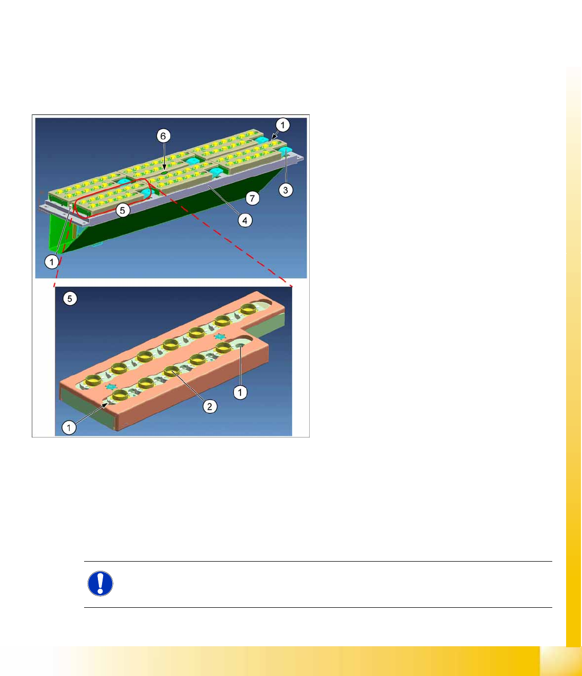
3.2.9.3 Nozzle Changer for C&P20 Head
The nozzle changer consists of at least six and up to twelve magazines, each of which has twelve nozzle
garages. The magazines are seated on a support. Each magazine is fixed with the help of a snap
fastener and can be released with a lever.
Each garage can be configured with different nozzle types.
Head Modularity Note
3-26: Nozzle changer and nozzle magazines
Legend
1. Calibration fiducials
2. Nozzle garage
3. Unlocking lever
4. Magazine support
5. Magazines
6. LED green (magazine query)
7. Changeover table side
Between changeover table and 1st row. The
nozzle reject bin is located on the right, next to
the 1st row.
Optionally, a nozzle changer can be installed for
the placement heads. This enables the nozzle
configuration to be changed quickly, thus allowing
the Collect&Place head to be quickly adapted to
the needs of the placement process.
NOTE:
The new nozzle changer carriers are identical for the C&P20A and CPP heads. This means that
you only need to change the magazines for head modularity.
Overview
Overview of Components Twin Head
Student Guide (FSE) SIPLACE X Series and X4I
Overview Edition 01/2009 EN
80
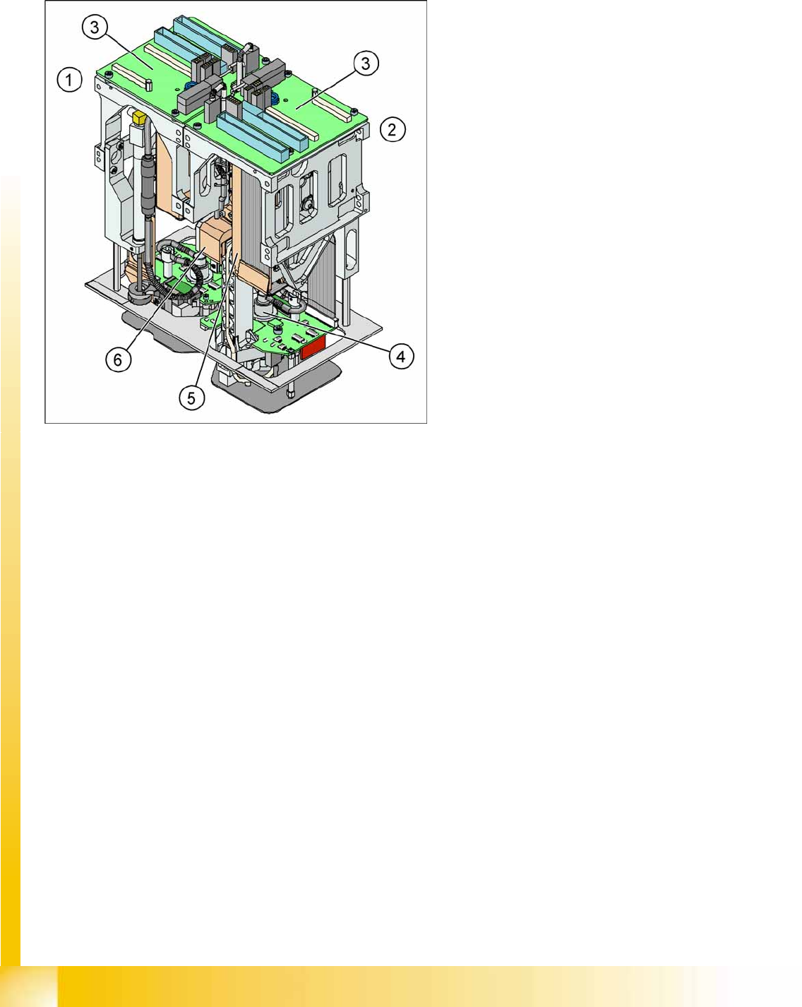
3.2.10 Twin Head
3.2.10.1 Description
3-27: Twin Head
Legend
1. Module 1
2. Module 2, rotate by 180 ° compared to module
1.
3. Main board on modul 1 and modul 2
4. D Axis
5. Linear motorZ Axis
6. Z axis incremental measurement system
The Twin head consists of two P&P heads of the
same model, which work according to the
Pick&Place principle. The second P&P head is
installed on the gantry, at a rotation of 180
degrees. One component after another can be
picked up per P&P, from the feeder module and be
optically centered by the stationary camera. On
the way to the placement position, the
components are rotated into the correct position.
They are then carefully positioned onto the board,
with great precision and with the help of a
regulated air blast and preset force.
Type 5xx nozzles are used for the Twin head.
Type 4xx nozzles for the P&P head and type 8xx
and 9xx nozzles for the C&P heads can be used
with an adapter.
Overview
Twin Head Overview of Components
Student Guide (FSE) SIPLACE X Series and X4I
Edition 01/2009 EN Overview
81
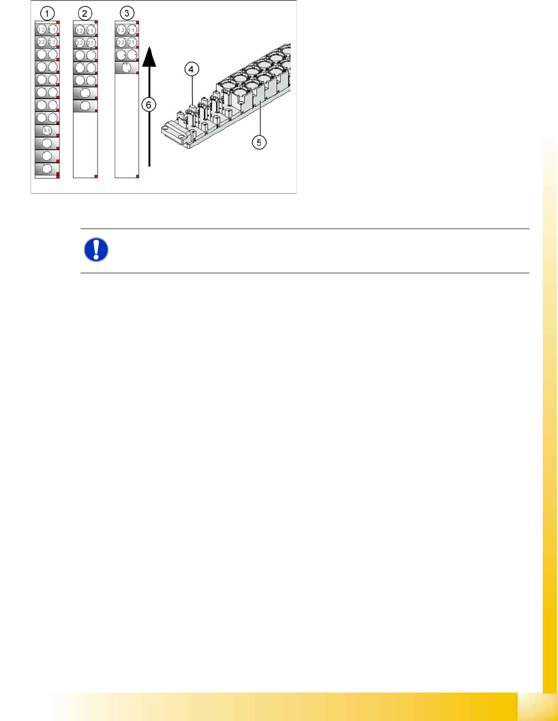
3.2.10.2 Nozzle Changer for Twin Head
3-28: Nozzle Changer for Twin head
SIPLACE X machines, equipped with a Twin head,
have one nozzle changer as a standard. This
nozzle changer is then installed in either sector 3
or sector 1.
The nozzle changer for a Twin head consists of a
standard module with 3 garages, each holding two
standard nozzles and one garage, holding one
special nozzle (see diagram).
Legend
1. Complete Nozzle changer
2. Extended Nozzle changer
3. Standard nozzle changer
NOTE:
If required, the above mentioned configurations can be changed and other magazines for
standard or special nozzles can be added individually.