00196044-05 - sg x und x4i fse_en.pdf - 第82页
Overview Overview of Components CPP Head S tudent Guide (FSE) SI PL ACE X Series and X4I Overview Edition 01/2009 EN 82 3.2.1 1 CPP Head 3.2.1 1.1 Overview T echnical Dat a A mixed mode between Collect&Place and Pick…
Overview
Twin Head Overview of Components
Student Guide (FSE) SIPLACE X Series and X4I
Edition 01/2009 EN Overview
81
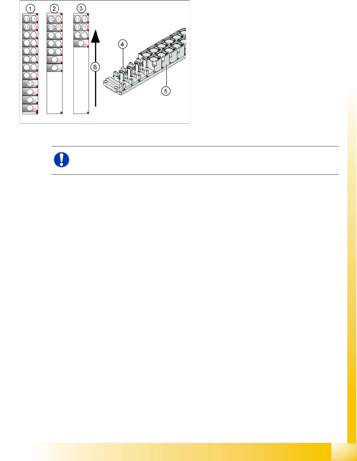
3.2.10.2 Nozzle Changer for Twin Head
3-28: Nozzle Changer for Twin head
SIPLACE X machines, equipped with a Twin head,
have one nozzle changer as a standard. This
nozzle changer is then installed in either sector 3
or sector 1.
The nozzle changer for a Twin head consists of a
standard module with 3 garages, each holding two
standard nozzles and one garage, holding one
special nozzle (see diagram).
Legend
1. Complete Nozzle changer
2. Extended Nozzle changer
3. Standard nozzle changer
NOTE:
If required, the above mentioned configurations can be changed and other magazines for
standard or special nozzles can be added individually.
Overview
Overview of Components CPP Head
Student Guide (FSE) SIPLACE X Series and X4I
Overview Edition 01/2009 EN
82
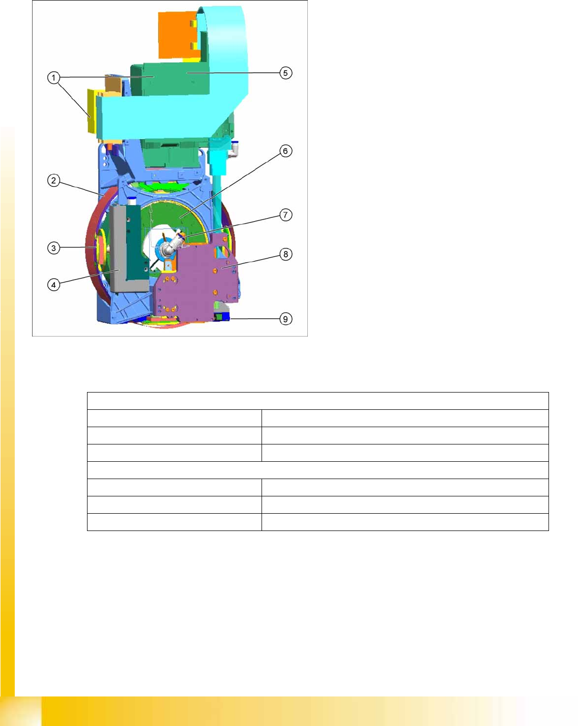
3.2.11 CPP Head
3.2.11.1 Overview
Technical Data
A mixed mode between Collect&Place and Pick&Place is also possible.
3-29: CPP head overview
CPP head (without component camera)
[03053528-xx]
Legend
1. Intermediate distributor 1 and 2
2. Star motor (integrated in head housing)
3. DP axis (as direct drive)
4. Pressure Control Valve
5. Component camera (standard: SST29)
6. Single Core Solution (SCS) – control DP
drives
7. Hold circuit with venturi nozzles and valve
terminal
8. Z axis with return cylinder
9. Component sensor in the pick and place
position
In Collect&Place mode
Component spectrum 01005 to 27x27 mm, up to 8.5 mm height
Speed Up to 24.000 cph
X/Y accuracy +/- 55 µm for 4 (sigma)
In Pick&Place mode
Component spectrum 01005 to 50x40 mm, up to 11.5 mm height
Speed Up to 1.500 cph
X/Y accuracy +/- 45 µm for 4 (sigma)
Overview
CPP Head Overview of Components
Student Guide (FSE) SIPLACE X Series and X4I
Edition 01/2009 EN Overview
83
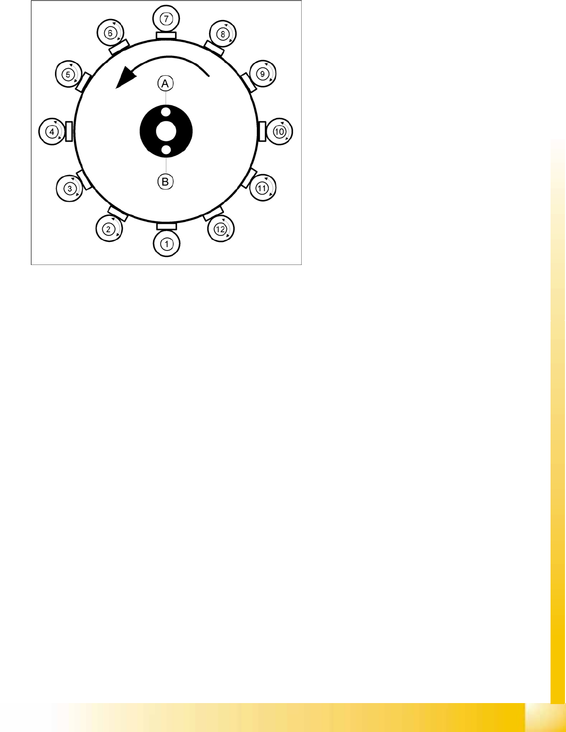
3.2.11.2 Overview of Functions
Star station 1:
Component pickup, placement or rejection
Component sensor: This checks whether the component is present after pickup and before
placement.
Component sensor: This checks whether there is no component present before pickup and after
placement.
Vacuum/air blast measurement for pickup/placement circuit
Star station 7:
Optical measurement of components
Vacuum measurement for holding circuit: By rotating the star axis, the vacuum value can be
measured at each segment.
Star station 2 - 6
In these star stations, the component at the segment can be rotated into the programmed placement
position.
Star station 8 -12
In star stations 8 - 12, angular correction is performed after optical measurement.
Star stations 2 - 6 and 8 - 12
Rotation to the correct pickup angle can be performed at any of the star stations, except 1 and 7.
Legend
A : Vacuum measurement hold circuit
B : Vacuum measurement of pick and place
circuit
1-12: star stations 1 to 12