00196044-05 - sg x und x4i fse_en.pdf - 第83页
Overview CPP Head Overview of Components S tudent Guide (FSE) SIPL ACE X Series and X4I Edition 01/2009 EN Overview 83 3.2.1 1.2 Overview of Functions Star station 1: Component pickup, placement or re jection Compone…
Overview
Overview of Components CPP Head
Student Guide (FSE) SIPLACE X Series and X4I
Overview Edition 01/2009 EN
82
3.2.11 CPP Head
3.2.11.1 Overview
Technical Data
A mixed mode between Collect&Place and Pick&Place is also possible.
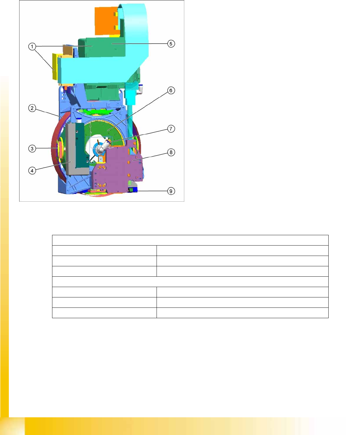
3-29: CPP head overview
CPP head (without component camera)
[03053528-xx]
Legend
1. Intermediate distributor 1 and 2
2. Star motor (integrated in head housing)
3. DP axis (as direct drive)
4. Pressure Control Valve
5. Component camera (standard: SST29)
6. Single Core Solution (SCS) – control DP
drives
7. Hold circuit with venturi nozzles and valve
terminal
8. Z axis with return cylinder
9. Component sensor in the pick and place
position
In Collect&Place mode
Component spectrum 01005 to 27x27 mm, up to 8.5 mm height
Speed Up to 24.000 cph
X/Y accuracy +/- 55 µm for 4 (sigma)
In Pick&Place mode
Component spectrum 01005 to 50x40 mm, up to 11.5 mm height
Speed Up to 1.500 cph
X/Y accuracy +/- 45 µm for 4 (sigma)
Overview
CPP Head Overview of Components
Student Guide (FSE) SIPLACE X Series and X4I
Edition 01/2009 EN Overview
83
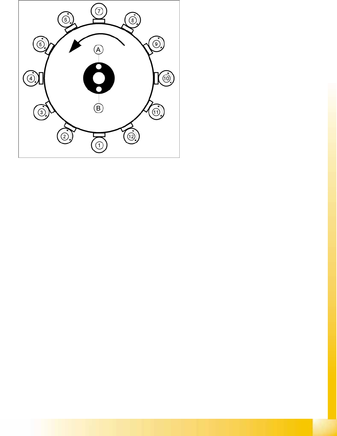
3.2.11.2 Overview of Functions
Star station 1:
Component pickup, placement or rejection
Component sensor: This checks whether the component is present after pickup and before
placement.
Component sensor: This checks whether there is no component present before pickup and after
placement.
Vacuum/air blast measurement for pickup/placement circuit
Star station 7:
Optical measurement of components
Vacuum measurement for holding circuit: By rotating the star axis, the vacuum value can be
measured at each segment.
Star station 2 - 6
In these star stations, the component at the segment can be rotated into the programmed placement
position.
Star station 8 -12
In star stations 8 - 12, angular correction is performed after optical measurement.
Star stations 2 - 6 and 8 - 12
Rotation to the correct pickup angle can be performed at any of the star stations, except 1 and 7.
Legend
A : Vacuum measurement hold circuit
B : Vacuum measurement of pick and place
circuit
1-12: star stations 1 to 12

Overview
Overview of Components CPP Head
Student Guide (FSE) SIPLACE X Series and X4I
Overview Edition 01/2009 EN
84
3.2.11.3 Description
The CPP head can be operated in various placement modes. The standard mode for the CPP head is
Collect&Place. This is possible up to a component size of 27 mm x 27 mm. The two additional placement
modes, mixed mode for medium/sized components (up to 32 mm x 32 mm) and Pick&Place mode for
large components (up to 50 mm x 40 mm) have significantly increased the component spectrum.
A maximum of twelve components can be picked up from the feeders (X feeders). This value also
depends on the component spectrum.
The component sensor checks the pickup/place positions, to see whether a component has been taken
by the nozzle or placed on a board. On the way to the placement position, the components are rotated
into the correct placement position and optically centered. This is performed with the digital component
camera on the head or, for medium/sized and large components, via a stationary camera. Before
placement is performed, the angle and X/Y position correction, determined by the Vision system, is
applied. The X/Y position correction is calculated into the placement position, while the angle correction
is applied separately to each segment. This is possible as each segment can be rotated independently
of the star position. The components are then carefully and accurately placed down on the board, with
an air blast.
Features:
Each segment has its own DP drive for rotating of the components into the correct position. The
segments are therefore no longer rotated into the correct angle in one single star position but can
now be rotated separately from one another.
Each segment has its own vacuum generator.
The so/called valve terminal is used to switch the supply pressure on and off for each segment. This
reduces the compressed air consumption by up to 40-50%.
In addition, each DP drive has a light barrier Z down. There is no moving cable during the upwards
and downwards movement of the Z axis.
The Z drive for the segments is realized via a linear motor with linear position measuring system.
The secondary part is now integrated into the Y axis, meaning that there is no moving cable during
the upwards and downwards movement of the Z axis.