00196044-05 - sg x und x4i fse_en.pdf - 第99页
Communication and Control Checking the Network Addresses Networking Address S tudent Guide (FSE) SIPL ACE X Series and X4I Edition 01/2009 EN Communication and Control 99 4-6: Network connections X Right-click with the m…
Communication and Control
Networking Address Checking the Network Addresses
Student Guide (FSE) SIPLACE X Series and X4I
Communication and Control Edition 01/2009 EN
98
4-3: Network cards in the station computer
Legend
4.2.1.2 Vision Computer Box PC
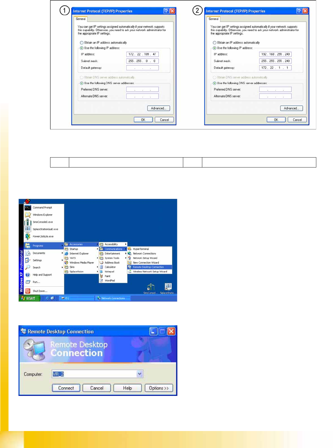
1 External IP address for SC 2 Internal IP address for SC
4-4: Remote desktop connection
The Vision computer has two network cards,
which can be directly set in Windows:
Access to the Vision computer is possible via a
Remote desktop connection
.
X For this, select
Start – Programs –
Accessories – Communications – Remote
Desktop Connection
.
4-5: Remote desktop connection
X Enter the computer name
VR_2
and select
Connect
.
You will now see the Windows XP basic view for
the Vision computer.
X Select
Start --> Settings --> Network
connections
.
Communication and Control
Checking the Network Addresses Networking Address
Student Guide (FSE) SIPLACE X Series and X4I
Edition 01/2009 EN Communication and Control
99
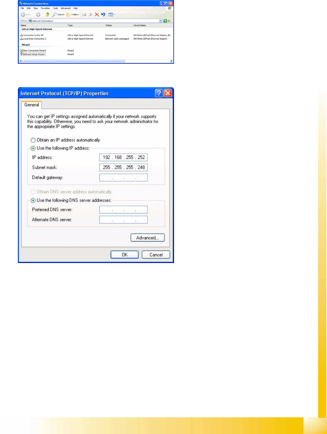
4-6: Network connections
X Right-click with the mouse on the network card
Connection to the SR
and select
Select
Properties
.
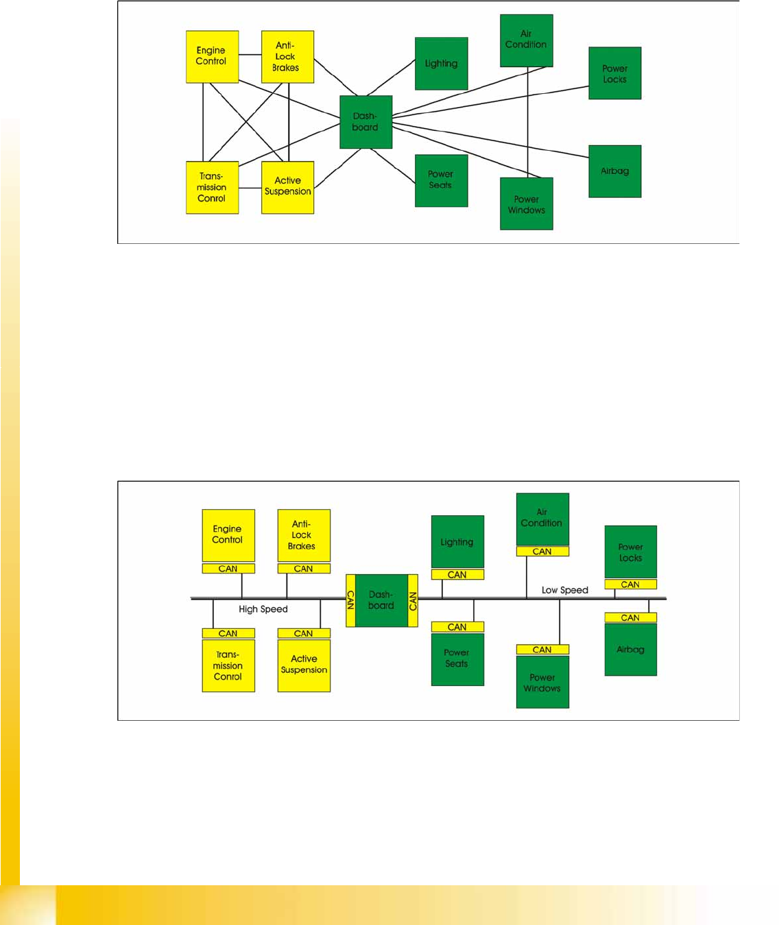
4-7: Internet protocol properties
X Select
Internet Protocol (TCP/IP)
from the
list and click on
Select Properties
.
Network card 1: Connection to the SR:
The network connection between the Vision
computer and station computer is established
via the LAN 1 connection of both computers.
The network address is pre-fixed and may not
be changed.
IP-Address Vision computer: 192.168.255.252
This TCP/IP address can only be checked or
changed by the system administrator.
Network card 2: Local Area Connection 2:
This connection is not used.
Communication and Control
CAN Bus Checking the Network Addresses
Student Guide (FSE) SIPLACE X Series and X4I
Communication and Control Edition 01/2009 EN
100
4.3 CAN Bus
The development of CAN began when more and more electronic devices were implemented into modern
motor vehicles. All this means more safety and more comfort for the driver. Examples of such devices
include engine management systems, active control systems such as ABS, gear control, lighting control,
ventilation, air conditioning and central locking.
4-8: Communication via cable connection
To improve the behavior of the vehicle even further, it was necessary for the different control systems
(and their sensors) to exchange information. This was usually done by discrete interconnection of the
different systems (i.e. point to point wiring). The requirement for information exchange has then grown
to such an extent that a cable network with a length of up to several miles and many connectors was
required. This produced growing problems concerning material cost, production time and reliability.
The solution to this problem was the connection of the control systems via a serial bus system. This bus
had to fulfill some special requirements due to its usage in a vehicle. With the use of CAN, point-to-point
wiring is replaced by one serial bus Each module is given a CAN Bus connection. This is accomplished
by adding some CAN-specific hardware to each control unit that provides the ’rules’ or protocol for
transmitting- and receiving information via the bus.
4-9: Communication via CAN bus