00196449-04_UM_FCCS_digital_DE_EN.pdf - 第51页
2 White Balance Process for SIPLACE Digital Vision Camera 2.1 General Explanations Operating Manual / Bedienungsanleitung Camera Calibration FCCS digital Kamerakalibrierung FCCS digital 04/2020 51 2 White Balance Process…
1 Introduction
1.3 Staff qualifications and training
50 Operating Manual / Bedienungsanleitung Camera Calibration FCCS digital Kamerakalibrierung FCCS digital 04/2020
●
technical documentation
●
technical information
●
spare parts lists etc.
Registration for the MySIPLACE user group is very simple:
► At the head of the web site, click on and then on the Register
link.
► Fill in the registration form and send it off to us.
Soon afterwards, you will receive your access authorization with user name and password.
1.3 Staff qualifications and training
Qualified or adequately trained personnel means that these people are familiar with the setting up,
operation and maintenance of the machine and the add-on devices and are suitably qualified, e.g.:
●
Have been trained, instructed or authorized to switch on and off, isolate, earth and identify
electrical circuits and system components in accordance with normal safety standards.
●
Have been trained or instructed in the upkeep and use of appropriate safety equipment in
accordance with normal safety standards.
1.4 Abbreviations
Abbreviations Description
PA, PA1, PA2 Placement area, Placement area 1, Placement area 2
CO Component
C&P Collect&Place
C&P12, CP12 Collect&Place head with 12 segments
C&P20, CP20 Collect&Place head with 20 segments
C&P20/A/M Collective term for C&P20, C&P20 A and C&P20 M
C&P20/A/M/P Collective term for C&P20, C&P20A, C&P20M and C&P20P
C&P6, CP6 Collect&Place head with 6 segments
CPP Collect&Pick&Place head
CPx Collective term for CPP, CP20, CP12 and/or CP6
ESD Electrostatic sensitive device
PCB Board
P&P Pick&Place
NC Nozzle changer
SC Station computer

2 White Balance Process for SIPLACE Digital Vision Camera
2.1 General Explanations
Operating Manual / Bedienungsanleitung Camera Calibration FCCS digital Kamerakalibrierung FCCS digital 04/2020 51
2 White Balance Process for SIPLACE Digital
Vision Camera
2.1 General Explanations
This manual describes the calibration and setting procedures for the digital SIPLACE cameras.
Due to the aging process of electronic components, the brightness of SIPLACE cameras changes
over long periods of use. For this reason, it is recommended to verify and calibrate the different
cameras approximately every year. This will considerably improve the production quality. It is par-
ticularly important, especially for central databases, to ensure that the brightness does not differ too
much between individual cameras of the same type. During calibration, the ratio between bright-
ness and flash duration is measured and the white standards are used to correct the flash duration
for each illumination level.
All digital cameras used in machine types SIPLACE X-Series, X-Series S (micron), SX-Series
(V2,V3), DX-Series, TX-Series V1/V2 (micron), E-Series and D-Series from SW version 605.xx or
SW705.03 onwards can be calibrated. (PCB cameras, component cameras and stationary cam-
eras).
This service work can be carried out by trained and certified production personnel as well by
SIPLACE service technicians.
CAUTION
Re-teaching
Please note that by calibrating the camera illumination levels they are practically new. In
some cases this may require re-teaching for certain component shapes due to modifica-
tions to the illumination.
Therefore, we recommend that you calibrate the cameras of a complete SMD line instead
of just for one individual machine.
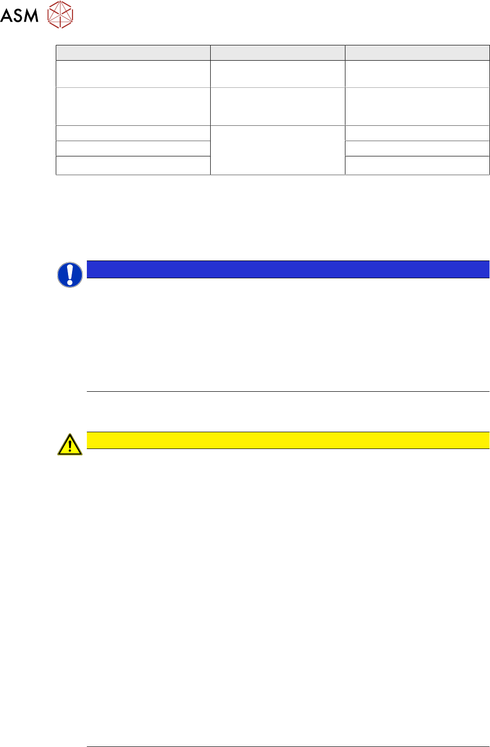
2.2 Calibratable Cameras
Camera type SST Machine type Placement head with nozzle
PCB camera SST24
(multicolor illumination option)
SIPLACE X-Series (micron) /
D-Series from SW version
605.xx or from SW705.03 /
SX-Series (V2,V3) / DX-
Series
---
PCB camera SST34
(standard illumination)
C&P20 component camera
SST23
SIPLACE X-Series / SX-
Series / X-Series S/TX V1
C&P20 with 1135 nozzle
C&P20 M component camera
SST41
SIPLACE CA-Series /
X4 S micron / X4i S micron
C&P20 M with 1135 nozzle
C&P20 P component camera
SST23 / SST41 option (C&P20
M2)
SIPLACE X-Series S / SX-
Series / TX V1
C&P20 P with 4135 nozzle
C&P20P2 component camera
SST48 C&P20 M3)
TX-Series / X-Series S / SX-
Series
C&P20P2 with nozzles 4235
C&P12 SST38 option SIPLACE X-Series / D-
Series / DX-Series
C&P12 with 920 nozzle
C&P12 SST29 / SST30 Option
C&P12 SST28 standard
C&P6 SST29 standard SIPLACE X-Series / D-
Series
C&P6 with 820 nozzle
CPP SST29 / SST30 Standard SIPLACE X-Series / SX-
Series / X-Series S / TX-
Series
CPP with 2035 nozzle
2 White Balance Process for SIPLACE Digital Vision Camera
2.3 Safety Instructions
52 Operating Manual / Bedienungsanleitung Camera Calibration FCCS digital Kamerakalibrierung FCCS digital 04/2020
Camera type SST Machine type Placement head with nozzle
CPP SST38 Option SIPLACE X-Series / SX-
Series / X-Series S
CPP with 2035 nozzle
CPP /CPP M SST45 SIPLACE CA V2 / TX mi-
cron / SX-Series / X-Series
S / TX-Series
CPP /CPP M
TWIN (P&P) SST33 SIPLACE X-Series / D-
Series / SX-Series / DX-
Series / X-Series S / TX-
Series
TWIN with 519 nozzle
P&P SST36 P&P with 519 nozzle
TWIN (P&P) SST25 option TWIN (P&P) with 519 nozzle
From SC/MC 605.xx and station software 705.03 the illumination setting for the digital cameras is
integrated into the station software interface and can be accessed with the SIPLACE FSE pass-
word. The password is provided to trained and certified customer personnel.
The menus for illumination calibration or for reading out data are available as single steps for the
respective individual cameras and as a collective menu, for all cameras configured at the machine,
for complete machine calibration.
NOTICE
XML files
During the calibration with SC/MC SW605.xx two XML files for the white balance process
are created in folder C:\SR-Daten\FCCS; one before and one after the measurement.
► Gantry_1_CameraID_28_before_FCCS_2010_06_23_09_19_04.xml
► Gantry_1_CameraID_28_after_FCCS_2010_06_23_09_19_16.xml
ð If a calibration is carried out with SW 705.03 or higher, a report file will be gener-
ated.
ð Report_FCCS_SX2_00004133_2011-01-31_15-20-40.pdf
2.3 Safety Instructions
CAUTION
The safety instructions in the chapter Operational Safety in the operating and service
manual take priority.
The SIPLACE machines are supplied with line voltage.
Parts of the machine may therefore conduct dangerous voltage levels. In specific modules
the voltage is present inside the machine base even when the main switch is turned off.
Handling the machines improperly or touching parts thereof which conduct high voltage
may result in death or serious physical injury as well as extensive property damage.
Before you perform any work on the machine, shut down the operating system and then en-
sure that the machine is switched off at the main switch and is disconnected from the power
supply. In addition, the compressed air supply must be turned off at the main valve of the
compressed air unit, in the machine base, and the compressed air lines must be bled by
actuating the needle valve on the compressed air unit. The area around the linear motors
presents a risk of lethal injuries to persons wearing heart pacemakers. Observe the instruc-
tions in Chapter "Special safety instructions for working in the vicinity of powerful magnetic
fields" in the operating and service manuals.
Obey the applicable accident prevention regulations, DIN standards and special safety
codes of your country at all times.
Read and observe the instructions about residual voltages in Chapter "Operational Safety".
Always observe the ESD regulations described in Chapter "Operational Safety" of the oper-
ating guide.
While working on the machine, always secure the machine to prevent unauthorized reactiv-
ation or access by unauthorized persons, as described in Chapter "Locking the Machine...".
There is additional, higher risk of accident when working with the SITEST program. SITEST
may therefore only be started by specially authorized and trained persons.