00196449-04_UM_FCCS_digital_DE_EN.pdf - 第70页
4 Camera Calibration in Stations from SW705.03 4.5 Calibration sequence in SW 7xx.xx 70 Operating Manual / Bedienungsanleitung Camera Calibration FCCS digital Kamerakalibrierung FCCS digital 04/2020 Fig.33: Save and exi…
4 Camera Calibration in Stations from SW705.03
4.5 Calibration sequence in SW 7xx.xx
Operating Manual / Bedienungsanleitung Camera Calibration FCCS digital Kamerakalibrierung FCCS digital 04/2020 69
4.5 Calibration sequence in SW 7xx.xx
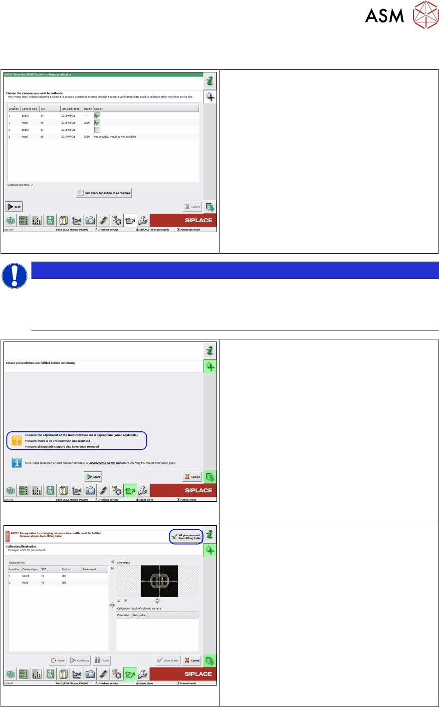
Fig.30: Select the cameras to be calibrated
► Select the cameras to be calibrated.
●
The nozzle types displayed in the column
must be available at the head and in the
nozzle changer. From 712.1 onwards and
when using the FCCS tool "03047943S04
camera calibration plate FCCS digital +",
the camera soiling will be checked before
the cameras are calibrated.
NOTICE
Is it possible to check the degree of soiling?
If an older FCCS tray is inserted, which does not have any pockets for the contrast stand-
ards, the software will recognize this, will not perform soiling checks and will omit this func-
tion without issuing an error message.
Fig.31: Starting conditions
► Before pressing the Start button make
sure that all pre-requisites mentioned
below are met.
Fig.32: All support pins removed from the lifting table
► Confirm that all conveyor pins have been
removed by selecting the All pins
removed from lifting table (top right) but-
ton.
► Now insert the camera calibration tray into
conveyor lane 1.
ð The calibration process will start auto-
matically after the tray has been
clamped in the placement area.
4 Camera Calibration in Stations from SW705.03
4.5 Calibration sequence in SW 7xx.xx
70 Operating Manual / Bedienungsanleitung Camera Calibration FCCS digital Kamerakalibrierung FCCS digital 04/2020
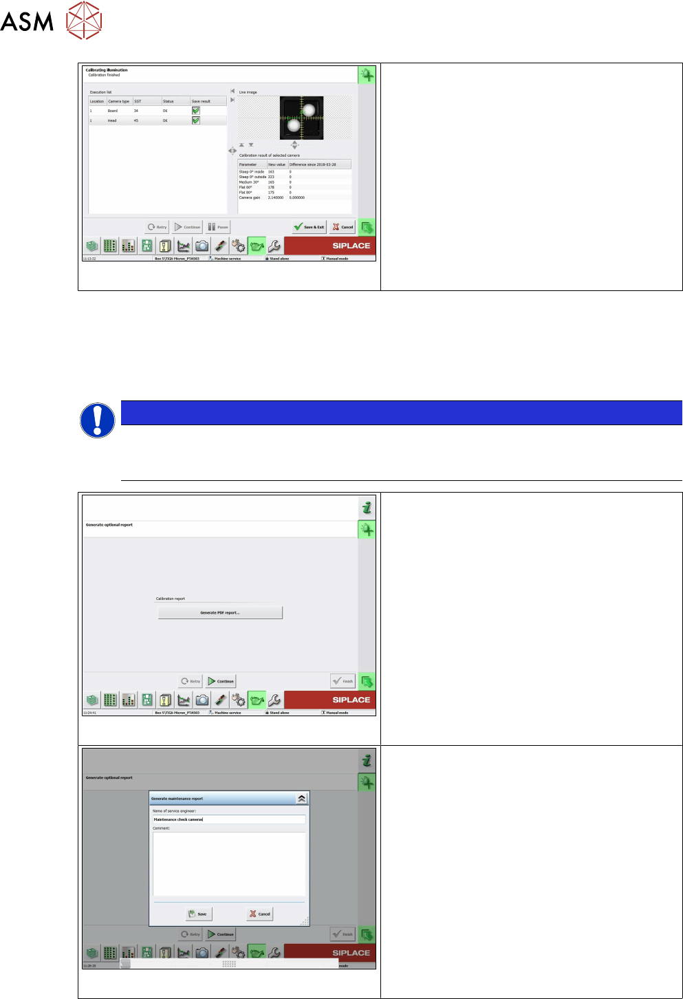
Fig.33: Save and exit
●
The camera soiling will be checked first.
●
• If the degree of camera soiling is more
than 66%, the function will be stopped with
an error message and the FCCS measure-
ments will not be started.
●
When the calibration is completed the
status will be displayed.
●
With the "Save&Exit" button the data will
be written into the cameras and you can
display the result in a file.
Error message 38423, camera soiled, "Camera is soiled and needs cleaning,camera: xx"
• If the degree of soiling is found to be tolerable, the software will automatically continue with FCCS
calibration. A (graphical) display with the degree of camera contamination will not be shown here
but can be seen later as a percentage in the FCCS report.
• The "Save&Exit" button only writes the FCCS calibration data to the cameras.
NOTICE
Cleaning the SIPLACE Vision camera system
The procedure for cleaning the SIPLACE Vision camera system is described in the tech-
nical information TI2014-10D09.pdf in German and in the TI2014-10E09.pdf file in English.
Fig.34: Creating a PDF report
●
Select the Generate PDF report... button
to show all camera calibration results in
tables.
●
For an explanation of the report file see 4.7
"Report File from SW 705.03 on-
wards" [}72].
Fig.35: Creating the report
●
As an option, you can create a report and
also add a comment.
●
• This report also shows the soiling results
for the cameras (see explanation of report
file).
4 Camera Calibration in Stations from SW705.03
4.6 Checking the camera soiling with contrast standard in the calibration tool pocket (without FCCS)
Operating Manual / Bedienungsanleitung Camera Calibration FCCS digital Kamerakalibrierung FCCS digital 04/2020 71
4.6 Checking the camera soiling with contrast standard in
the calibration tool pocket (without FCCS)
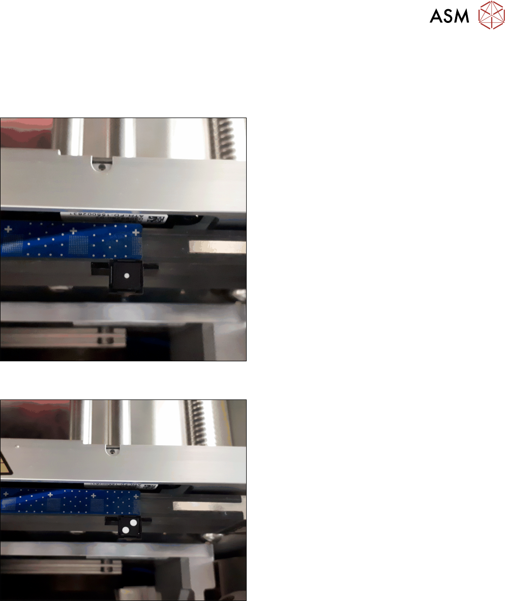
► Place the contrast standard into the calibration pocket. Observe the orientation of the contrast
standard.
Fig.36: Figure 3-1a: Measuring the component camera (head,
stationary)
► To measure a component camera (head cameras
or stationary cameras), place the standard into
the calibration pocket, with the two white dots fa-
cing downwards.
Fig.37: Figure 3-1b: Measuring PCB cameras
► To measure the PCB camera, place the contrast
standard into the calibration pocket, with the two
white dots facing upwards.
This new function is available from station software 712.1 in the →Maintenance → Verification
menu.