00196449-04_UM_FCCS_digital_DE_EN.pdf - 第72页
4 Camera Calibration in Stations from SW705.03 4.7 Report File from SW 705.03 onwards 72 Operating Manual / Bedienungsanleitung Camera Calibration FCCS digital Kamerakalibrierung FCCS digital 04/2020 Fig.38: Checking th…
4 Camera Calibration in Stations from SW705.03
4.6 Checking the camera soiling with contrast standard in the calibration tool pocket (without FCCS)
Operating Manual / Bedienungsanleitung Camera Calibration FCCS digital Kamerakalibrierung FCCS digital 04/2020 71
4.6 Checking the camera soiling with contrast standard in
the calibration tool pocket (without FCCS)
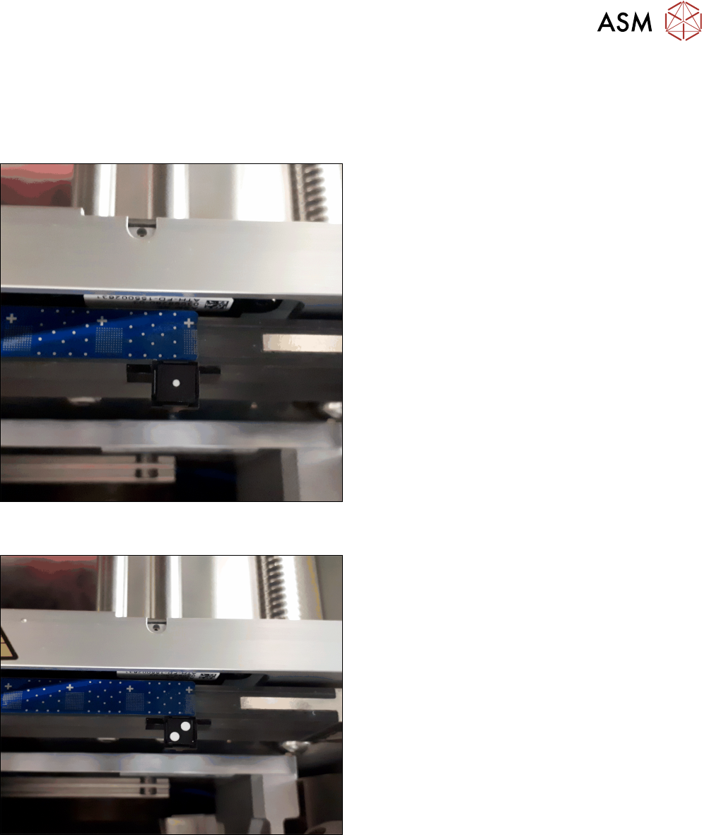
► Place the contrast standard into the calibration pocket. Observe the orientation of the contrast
standard.
Fig.36: Figure 3-1a: Measuring the component camera (head,
stationary)
► To measure a component camera (head cameras
or stationary cameras), place the standard into
the calibration pocket, with the two white dots fa-
cing downwards.
Fig.37: Figure 3-1b: Measuring PCB cameras
► To measure the PCB camera, place the contrast
standard into the calibration pocket, with the two
white dots facing upwards.
This new function is available from station software 712.1 in the →Maintenance → Verification
menu.
4 Camera Calibration in Stations from SW705.03
4.7 Report File from SW 705.03 onwards
72 Operating Manual / Bedienungsanleitung Camera Calibration FCCS digital Kamerakalibrierung FCCS digital 04/2020
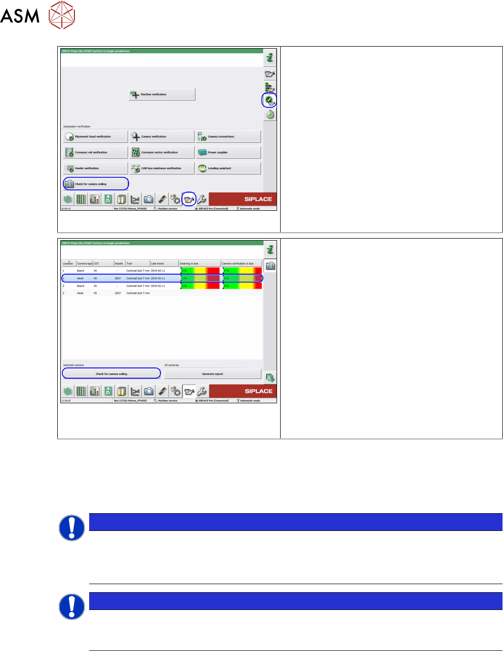
Fig.38: Checking the camera for soiling
ü The user level is Advanced production.
► Go to the Maintenance view.
► Select the Verification section.
► Click on the Check for camera soiling
button.
Fig.39: Checking the camera for soiling
ü The last result (if present) will be shown!
► Go to the Maintenance view.
► Select the camera to be measured.
► Place the contrast standard in the cali-
bration pocket and make sure that the con-
trast standard is correctly positioned.
► Click on the Check for camera soiling
button.
ð The result will be shown and can be
saved in a file on the station computer
with the Generate report function. This
same file is then saved via the LineDia-
gnostic software on the Siplace Pro
computer, in the MaintenanceReports
folder.
●
On the station computer: C:\Sirio\Work\MaintenanceReports
●
On the SIPLACE Pro computer: C:\MaintenanceReports
4.7 Report File from SW 705.03 onwards
NOTICE
From the above mentioned station software version onwards a report file will auto-
matically be generated after the calibration.
Example: Report_FCCS_SX2_00004133_2011-01-31_15-20-40 currently from
SW705-03.pdf
NOTICE
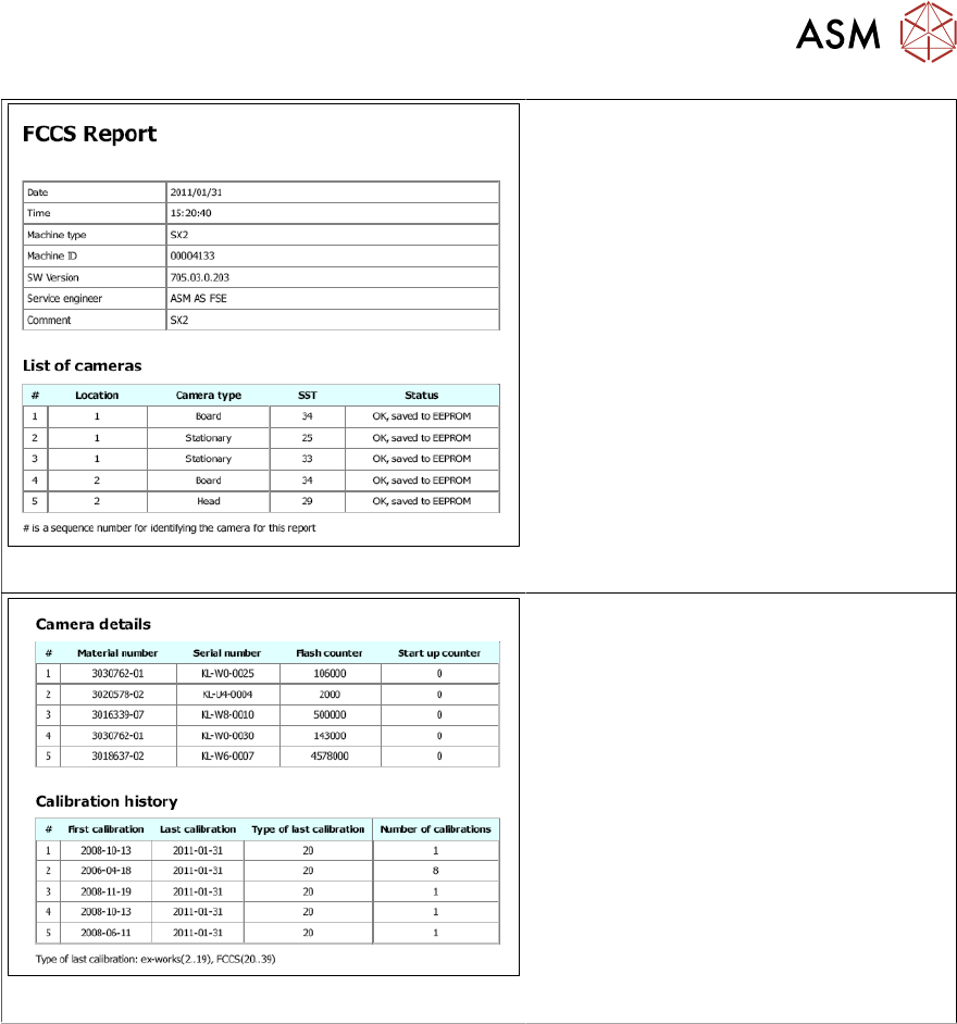
Example for a report file of a SIPLACE SX2 machine
The row numbers of the first table references the results of the relevant camera in the fol-
lowing tables.
4 Camera Calibration in Stations from SW705.03
4.7 Report File from SW 705.03 onwards
Operating Manual / Bedienungsanleitung Camera Calibration FCCS digital Kamerakalibrierung FCCS digital 04/2020 73
Fig.40: List of cameras
●
The list of cameras gives an overview
of the calibration states and the
proper storage of the calibration val-
ues.
Fig.41: Camera details and calibration history
●
The camera details show the mater-
ial number, the serial number and the
number of flashes, i.e. the number of
components that have been centered
optically.
●
The calibration history shows the
dates of the first and the last cali-
bration as well as the number of cali-
bration processes.