00198150-02_SM_TX_en.pdf - 第105页
6 Gantries 6.3 Trailing Cable and Printed Circuit Boards Service Manual SIPLACE TX Series 06/2017 105 Fig.123: Hoses ► Mark the positions of the hoses on both sides of the couplings (1) , so that these can be easily as…
6 Gantries
6.3 Trailing Cable and Printed Circuit Boards
104 Service Manual SIPLACE TX Series 06/2017
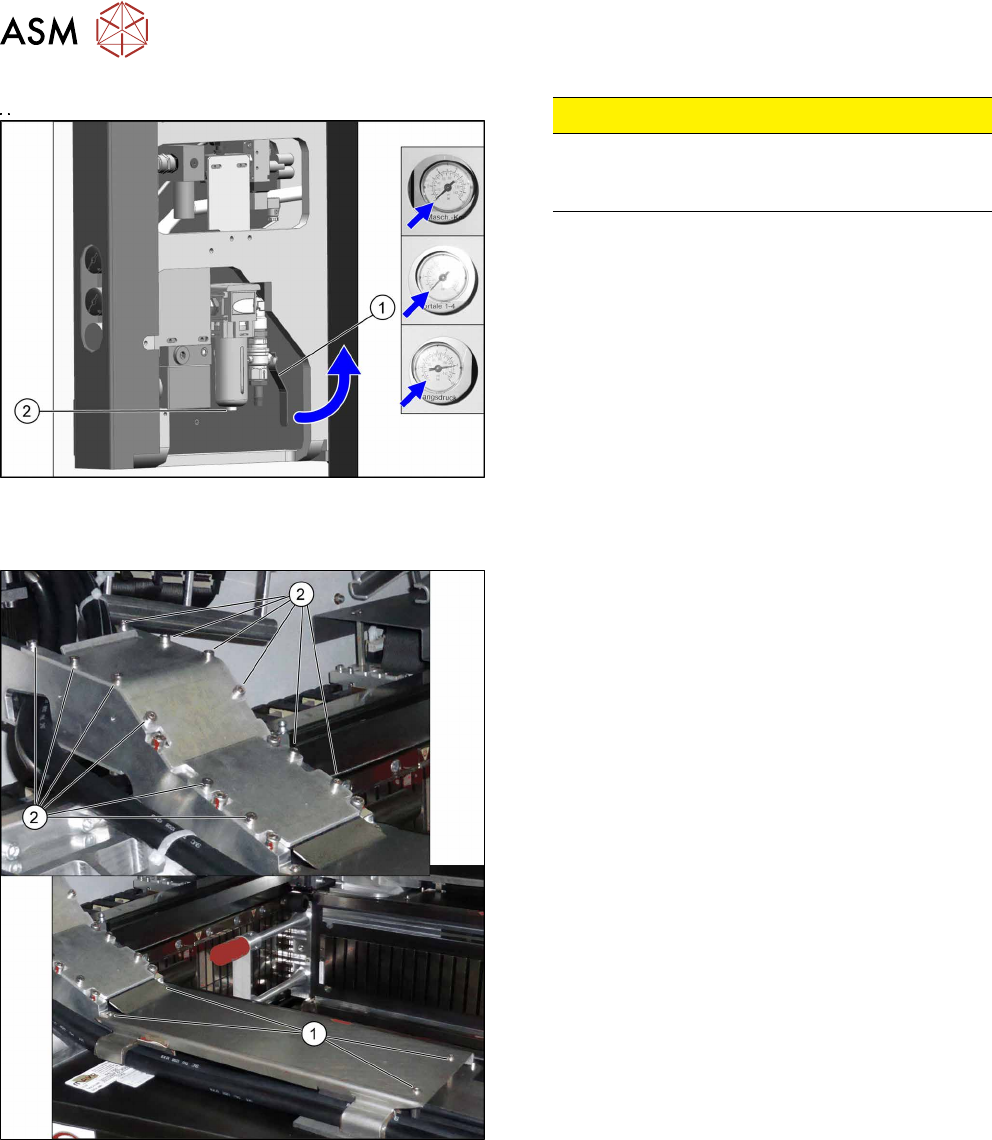
Fig.121: Disabling the compressed air supply
CAUTION!
Switch off the compressed air supply.
When working on the pneumatic system, always
switch off the compressed air supply.
.
► Push the lever (1) for the compressed air supply
back, until it is positioned horizontally.
► Open the screw (2) on the inlet filter to vent the
system. Hold a cloth underneath to capture any
escaping oil.
► All pressure gauges must be set to zero.
Dismantling the trailing cable and machine side
Fig.122: Covers
► Remove the four screws(1) and remove the
lower cover. These screws are not secured with
Loctite.
► Remove the twelve screws(2) and remove the
upper cover. These screws are secured with Loc-
tite241.
6 Gantries
6.3 Trailing Cable and Printed Circuit Boards
Service Manual SIPLACE TX Series 06/2017 105
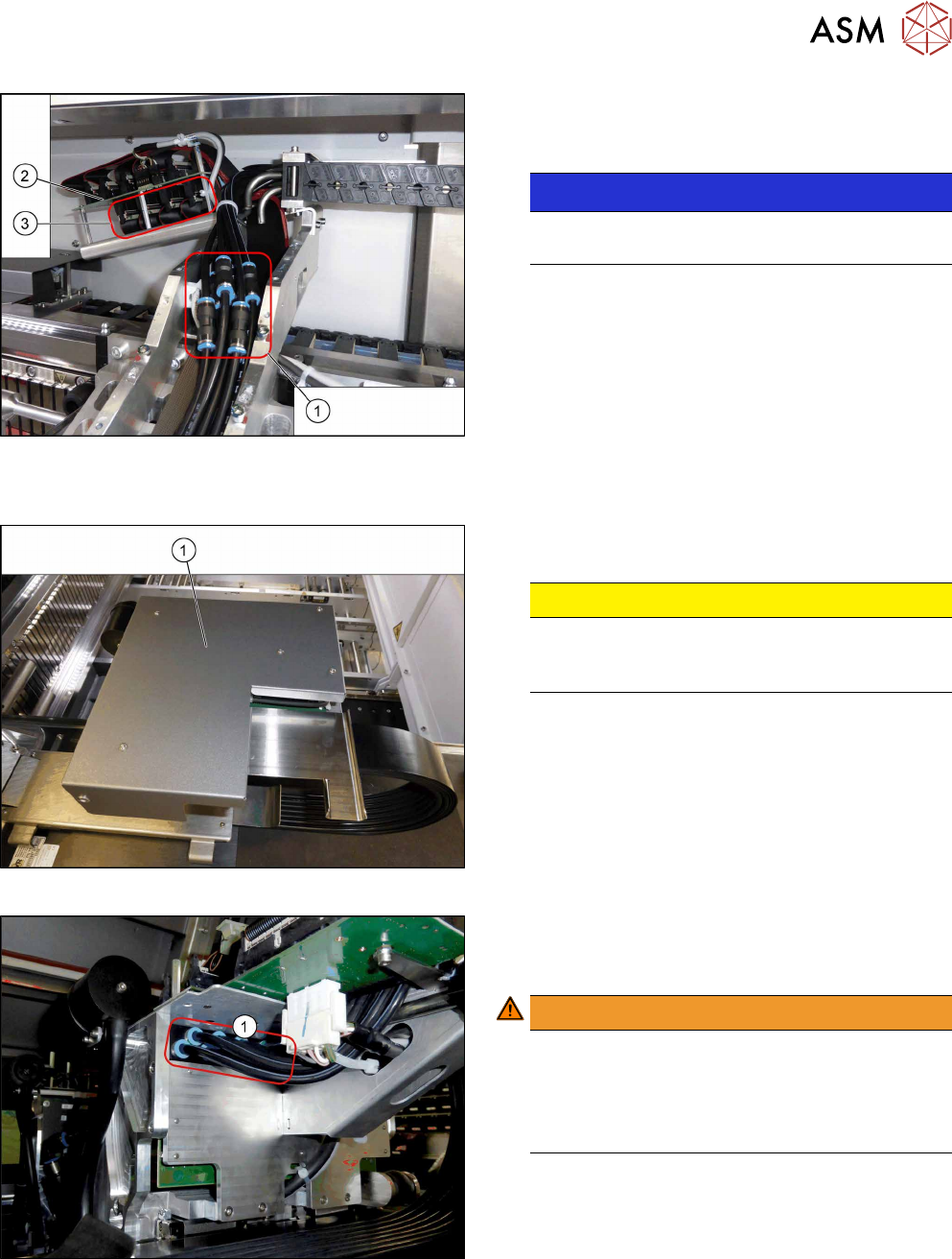
Fig.123: Hoses
► Mark the positions of the hoses on both sides of
the couplings(1), so that these can be easily as-
signed later on.
NOTICE!
Hose 1 is usually already marked.
Pay particular attention to hoses 1 and 2.
.
► Pull the hoses off the couplings.
► Mark the positions of the connectors(2) on the
gantry interface(3) so that these can be easily
assigned later on.
► Unplug the connector from the gantry interface
and unthread the cable.
Dismantling the trailing cable on the gantry side
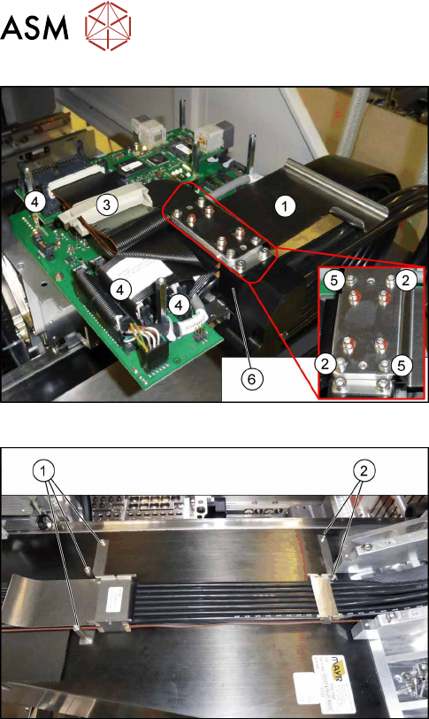
Fig.124: Board cover
► Remove the five fastening screws and lift the
board cover(1) off.
CAUTION!
Switch off the machine
To avoid short circuits, only dismantle the cover
when the machine is switched off!
.
Fig.125: Gantry distributor
► Pull the hoses off the gantry distributor(1). You
might like to mark their positions to make clear
assignment easier later on.
WARNING!
Risk of injury to hands
Use the "hose unlocking tool" for this
[03047090‑xx].
See also: 6.3.5 "Handling the Hose Unlocking
Tool [03047090-xx]" [}102]
.
6 Gantries
6.3 Trailing Cable and Printed Circuit Boards
106 Service Manual SIPLACE TX Series 06/2017
Fig.126: Holding-down device
► Remove the two screws (2) fastening the holding-
down device (1) and then remove the holding.-
down device.
► Open the cable clamp (3).
► Unplug the connectors (4). You might like to mark
their positions to make clear assignment easier
later on.
► Remove the two screws (5) fastening the trailing
cable clamp(6).
Fig.127: Trailing cable on the gantry
► Remove the three screws(1). These screws are
not secured with Loctite.
► Remove the two screws(2). These screws are
not secured with Loctite.
The trailing cable now lies loose in the machine.
► Carefully remove the trailing cable from the machine.