00198150-02_SM_TX_en.pdf - 第108页
6 Gantries 6.3 Trailing Cable and Printed Circuit Boards 108 Service Manual SIPLACE TX Series 06/2017 Fig.129: Trailing cable on the gantry CAUTION! Do not secure the screws(1) and(2) with Loctite. . 6.3.6.2 Replaci…
6 Gantries
6.3 Trailing Cable and Printed Circuit Boards
Service Manual SIPLACE TX Series 06/2017 107
Installation
► Installation is performed by following the above instructions in the reverse order. Also observe
the following instructions:
CAUTION
Installation instructions
► If a vacuum pump is fitted, also observe the relevant assembly instructions
[00196845‑xx].
► Always handle the new trailing cable with care.
► You might need to enlist the help of a second person.
► Make sure that the flat ribbon cable and the pneumatic hoses are not rubbed against
any parts or folded. Look out for sharp edges.
► Prepare the trailing cable. Place the old and new trailing cables next to one another
and match the length of the new trailing cable hose to the old one.
You might find it helpful to mark the new hoses and connectors in the same way as
the old ones.
► If hose ends were damaged during removal, cut these with hose cutters.
► Clean the trailing cable contact surface on the machine base with a dry cloth.
► Carefully insert the new trailing cable into the prescribed position. Make sure you do
not fold or twist the trailing cable.
► Secure screws with Loctite 241 (see below).
► Fit the board cover. Make sure that you do not cause a short circuit.
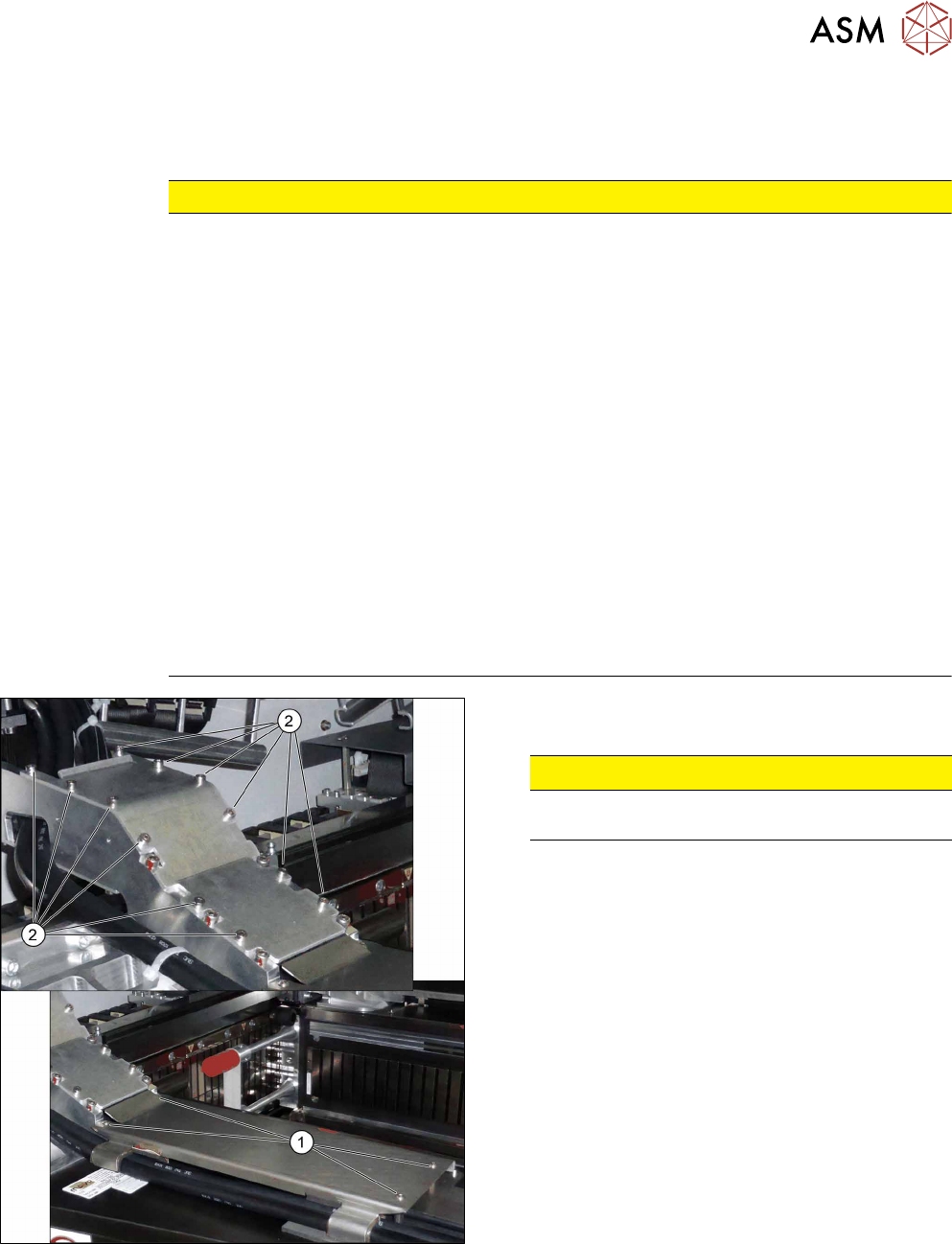
Fig.128: Covers
► Secure the screws(2) of the upper cover with
Loctite 241.
CAUTION!
Do not secure the screws(1) of the lower
cover with Loctite.
.
6 Gantries
6.3 Trailing Cable and Printed Circuit Boards
108 Service Manual SIPLACE TX Series 06/2017
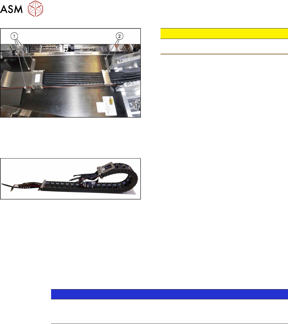
Fig.129: Trailing cable on the gantry
CAUTION!
Do not secure the screws(1) and(2) with
Loctite.
.
6.3.6.2 Replacing the Y Axis Trailing Cable
Parts, equipment and tools
Fig.130: Trailing cable
●
Trailing cable Y TX gantry 1 [03112680‑xx]
●
Trailing cable Y TX gantry 2 [03112675‑xx]
●
Hose unlocking tool [03047090-xx]
●
Pipe/hose cutters [00381443-xx]
●
If needed, assembly instructions "Vacuum pump option for SIPLACE TX-Series" [DE
+EN:00198147‑xx]
●
Loctite 241 [02101037‑xx]
●
Edding marker, white [00382740-xx]
●
You might find it advisable to enlist the help of a second person.
Removal
NOTICE
Vacuum pump
► When a vacuum pump is fitted, also observe the assembly instructions "SIPLACE TX
Vacuum Pump" [00198147‑xx].
► Switch off the machine, disconnect it from the power supply and secure it to prevent
unauthorized reactivation. Observe the instructions in section 1.2 "Preparatory Work..." [}15].
6 Gantries
6.3 Trailing Cable and Printed Circuit Boards
Service Manual SIPLACE TX Series 06/2017 109
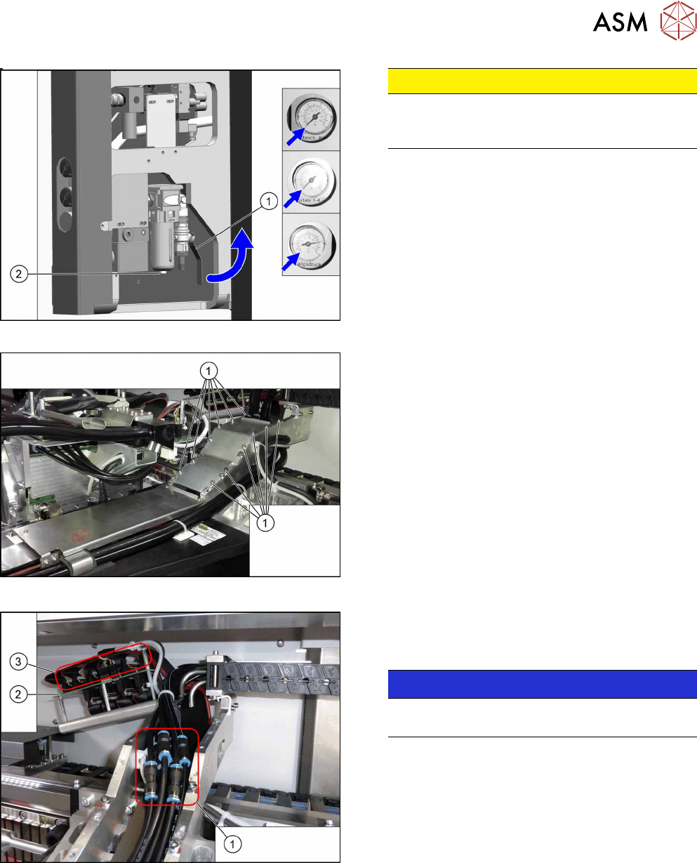
Fig.131: Disabling the compressed air supply
CAUTION!
Switch off the compressed air supply.
When working on the pneumatic system, always
switch off the compressed air supply.
.
► Push the lever (1) for the compressed air supply
back, until it is positioned horizontally.
► Open the screw (2) on the inlet filter to vent the
system. Hold a cloth underneath to capture any
escaping oil.
► All pressure gauges must be set to zero.
Fig.132: Cover
► Remove the twelve screws(1) and remove the
upper cover. These screws are secured with Loc-
tite241.
Fig.133: Hoses
► You might like to mark the positions of the hoses
on both sides of the couplings(1), so that these
can be easily assigned later on.
NOTICE!
Hose 1 usually is already marked.
Especially pay attention to hoses 1 and 2.
.
► Pull the hoses off the couplings.
► Mark the positions of the connectors(2) on the
gantry interface(3) so that these can be easily
assigned later on.
► Pull the connector off the gantry interface and un-
thread the cable.