00198150-02_SM_TX_en.pdf - 第122页
6 Gantries 6.4 MHCU, Boards and Camera 122 Service Manual SIPLACE TX Series 06/2017 Installation ► Follow the removal instructions in reverse order for installation. Also observe the following in- structions: CAUTION Ins…
6 Gantries
6.4 MHCU, Boards and Camera
Service Manual SIPLACE TX Series 06/2017 121
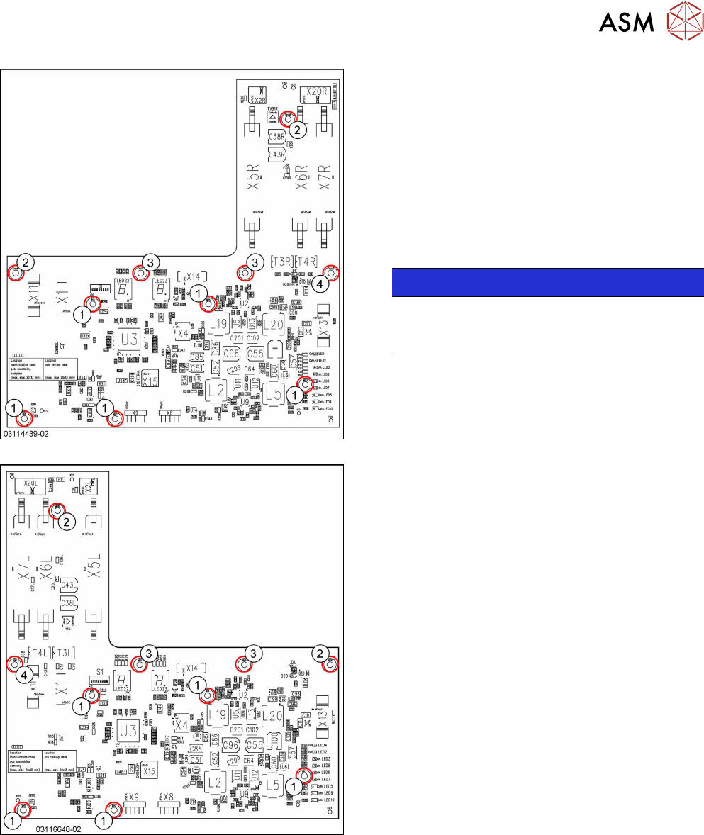
Fig.153: Head interface 1 TX
Fig.154: Head interface 2 TX
1. Spacer bolt M3x20 [03023427‑xx] (for VHI)
2. Spacer bolt M3x50 [03023503‑xx] (for cover)
3. Spacer bolt M3x15 with plastic cable clamp,
washer and screw
4. Nut M3 [03008162‑xx]
► Remove the screws and spacer bolts fastening
the head interface.
You may like to mark their positions, to make
clear assignment easier later on.
NOTICE!
Inverse layout
The layout of the two head interfaces is the
same, but inverse.
.
► Carefully remove the head interface. Make sure
that the connectors to the head adapter MHCU
are not damaged.
6 Gantries
6.4 MHCU, Boards and Camera
122 Service Manual SIPLACE TX Series 06/2017
Installation
► Follow the removal instructions in reverse order for installation. Also observe the following in-
structions:
CAUTION
Installation instructions
► Apply the DIP switch setting (see 6.4.4.1 "Head Interface 1/2" [}122]).
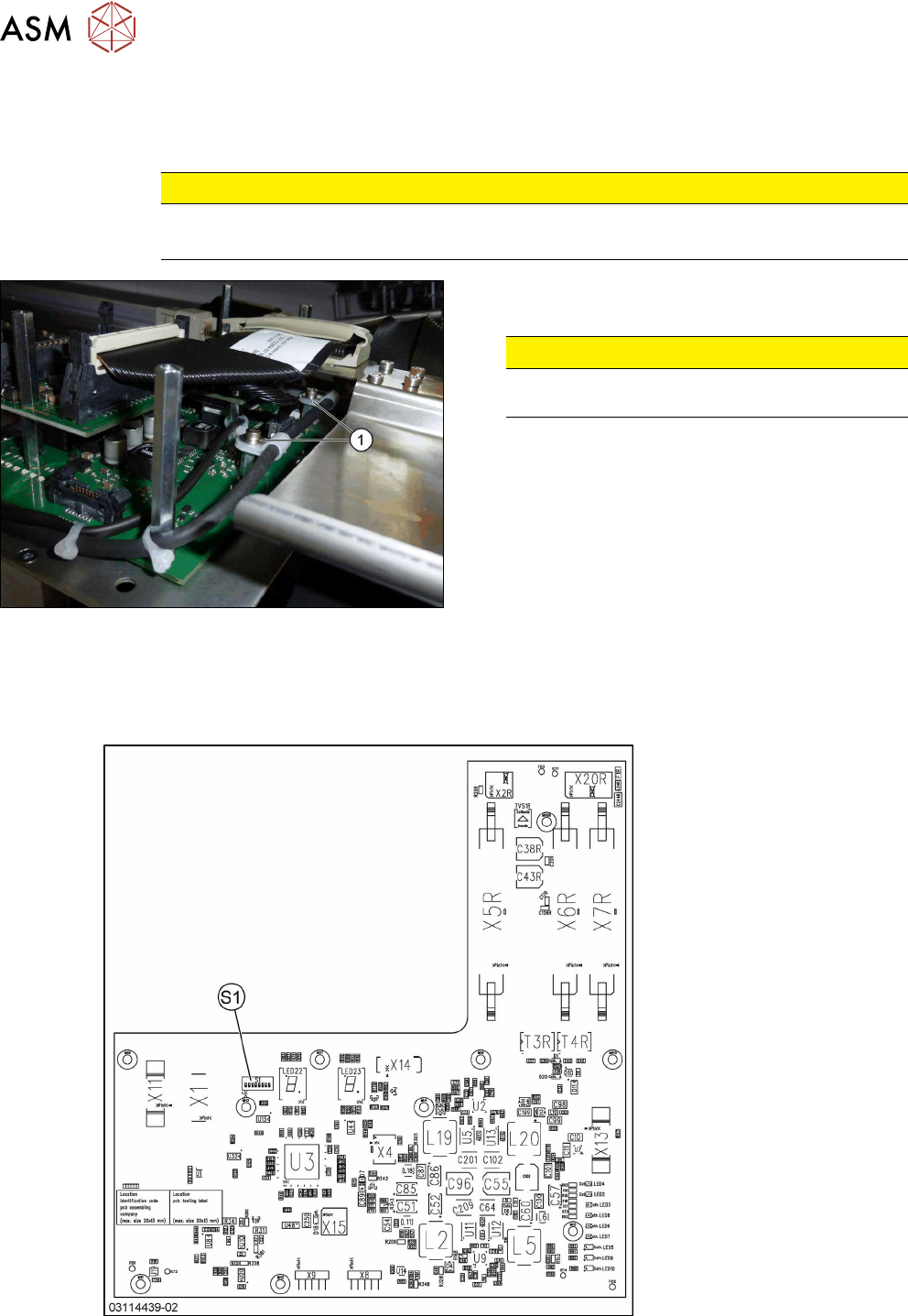
Fig.155: Securing screws
► Secure all screws with plastic cable holders(1)
with Loctite241.
CAUTION!
Do not secure screws with direct contact to
the board.
.
6.4.4.1 Head Interface 1/2
There are two head interface designs. Depending on the gantry, either the head interface 1 or 2 will
be used.
Fig.156: Head interface 1 TX
6 Gantries
6.4 MHCU, Boards and Camera
Service Manual SIPLACE TX Series 06/2017 123
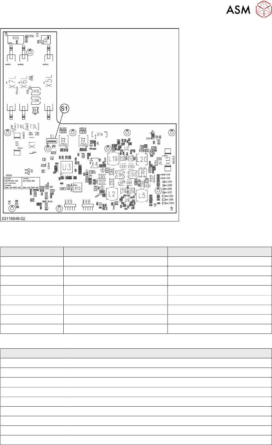
Fig.157: Head interface 2 TX
DIP switch S1 [03114439-02] [03116648-02]
DIP switches Gantry 1 Gantry 2
P0 OFF ON
P1 OFF OFF
BOOT OFF OFF
RES2 OFF OFF
RES1 OFF OFF
FAN OFF OFF
V-OFF OFF OFF
HCU_1 OFF OFF
LED [03114439-02] [03116648-02]
LED Description
X_TEMP X motor temperature
PF_BASE Power fail base
EM_STOP Emergency stop – safety circuit not closed
PF_LOC Power fail location
HCV1_ER MHCU1 error
HCV2_ERR MHCU2 error (only for Twin head)
HCV1_OK MHCU1 has booted and is ready
HCV2_OK MHCU2 has booted and OK
FPGA_OK FPGA booted and OK
The 7 segment display next to the DIP switch S1 provides information about MHCU1, the other 7
segment display is for MHCU 2 (if a Twin head is present).