00198150-02_SM_TX_en.pdf - 第131页
6 Gantries 6.4 MHCU, Boards and Camera Service Manual SIPLACE TX Series 06/2017 131 Fig.172: Select subsystem ► Select the subsystem for the eSW download. ► Click on the Continue button. Fig.173: Update machine menu 1.…
6 Gantries
6.4 MHCU, Boards and Camera
130 Service Manual SIPLACE TX Series 06/2017
6.4.11 eSW Download (SW 70x)
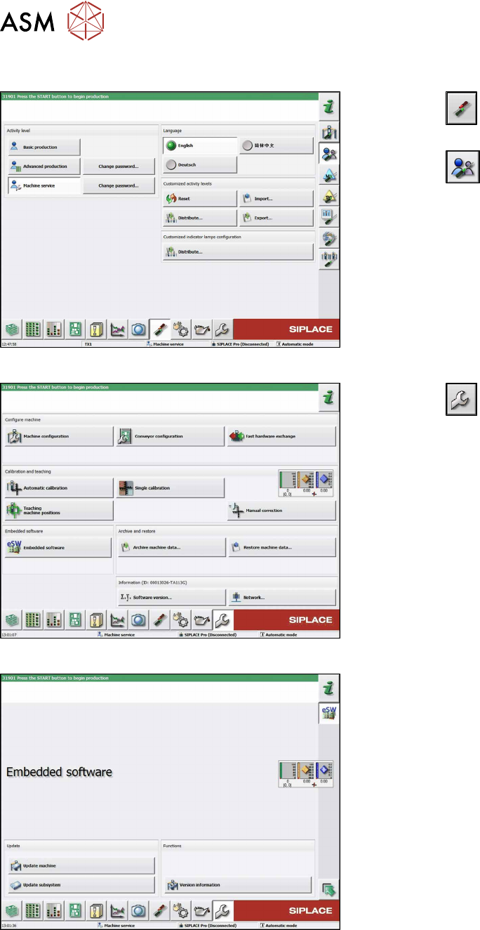
Fig.169: Select operator level
► Click the
button to enter the Settings
menu.
► Click the
button to open the Check and set
user settings menu.
► Switch to operator level Machine service or bet-
ter.
Fig.170: Service menu
► Click the
button to enter the Service menu.
► Click on the Embedded software button.
Fig.171: Embedded software menu
Select the required function:
► Click on Update machine… to check the entire
machine and to perform an eSW download for
multiple subsystems (see next picture).
► Click on Update subsystem… to select and
check one subsystem and to perform an eSW
download.
► Click on the button Version information…, to
view all versions of the subsystems, BIOS, ap-
plication 1/2/3/5.
6 Gantries
6.4 MHCU, Boards and Camera
Service Manual SIPLACE TX Series 06/2017 131
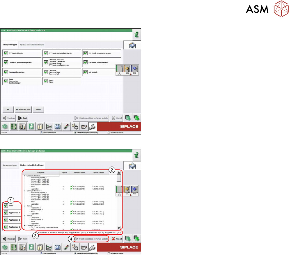
Fig.172: Select subsystem
► Select the subsystem for the eSW download.
► Click on the Continue button.
Fig.173: Update machine menu
1. Selection buttons:
BIOS
Application 1
Application 2
Application 3
2. Shows the status of the individual subsystems
3. Update information
This shows you the number of subsystems which
still need to be downloaded.
4. Starts the download
6 Gantries
6.5 Filter and Pneumatics
132 Service Manual SIPLACE TX Series 06/2017
6.5 Filter and Pneumatics
6.5.1 Gantries – Filter and Pneumatics – Overview
Fig.174: Filter and pneumatics
1. Cooling air filter
6.5.2 "Replacing the Cooling Air Filter [03018635-
xx]" [}132]
Replacing Filter Element / O-Ring
2. Pressure sensor vacuum
6.5.3 "Replacing Pressure Sensor Vacuum
[03108457-xx]" [}133]
6.5.2 Replacing the Cooling Air Filter [03018635-xx]
Parts, equipment and tools
●
Cooling air filter complete [03018635-xx]
●
Loctite 241 [02101037‑xx]
Removal
► Switch off the machine, disconnect it from the power supply and secure it to prevent
unauthorized reactivation. Observe the instructions in section 1.2 "Preparatory Work..." [}15].
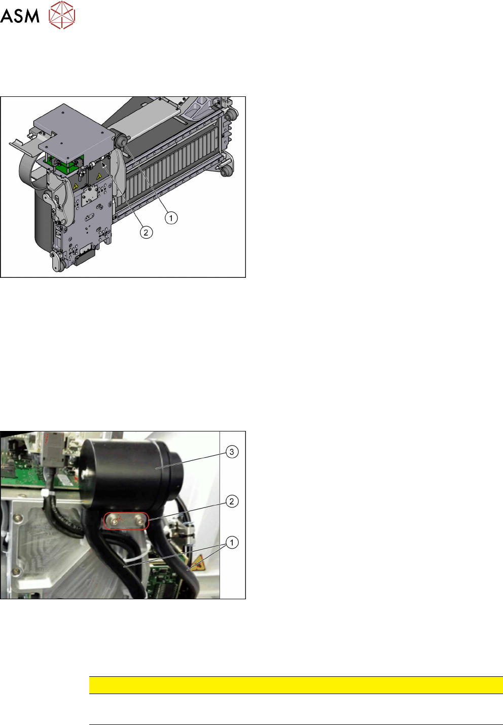
Fig.175: Cooling air filter
► Remove the two hoses(1).
► Remove the two screws(2) fastening the cooling
air filter (secured with Loctite 241).
► Remove the cooling air filter(3).
Installation
► Follow the removal instructions in reverse order for installation. Also observe the following in-
structions:
CAUTION
Installation instructions
► Secure screws with Loctite 241 where necessary.