00198150-02_SM_TX_en.pdf - 第132页
6 Gantries 6.5 Filter and Pneumatics 132 Service Manual SIPLACE TX Series 06/2017 6.5 Filter and Pneumatics 6.5.1 Gantries – Filter and Pneumatics – Overview Fig.174: Filter and pneumatics 1. Cooling air filter 6.5.2 &q…
6 Gantries
6.4 MHCU, Boards and Camera
Service Manual SIPLACE TX Series 06/2017 131
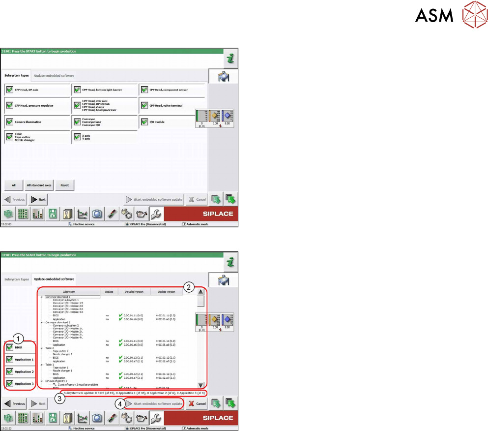
Fig.172: Select subsystem
► Select the subsystem for the eSW download.
► Click on the Continue button.
Fig.173: Update machine menu
1. Selection buttons:
BIOS
Application 1
Application 2
Application 3
2. Shows the status of the individual subsystems
3. Update information
This shows you the number of subsystems which
still need to be downloaded.
4. Starts the download
6 Gantries
6.5 Filter and Pneumatics
132 Service Manual SIPLACE TX Series 06/2017
6.5 Filter and Pneumatics
6.5.1 Gantries – Filter and Pneumatics – Overview
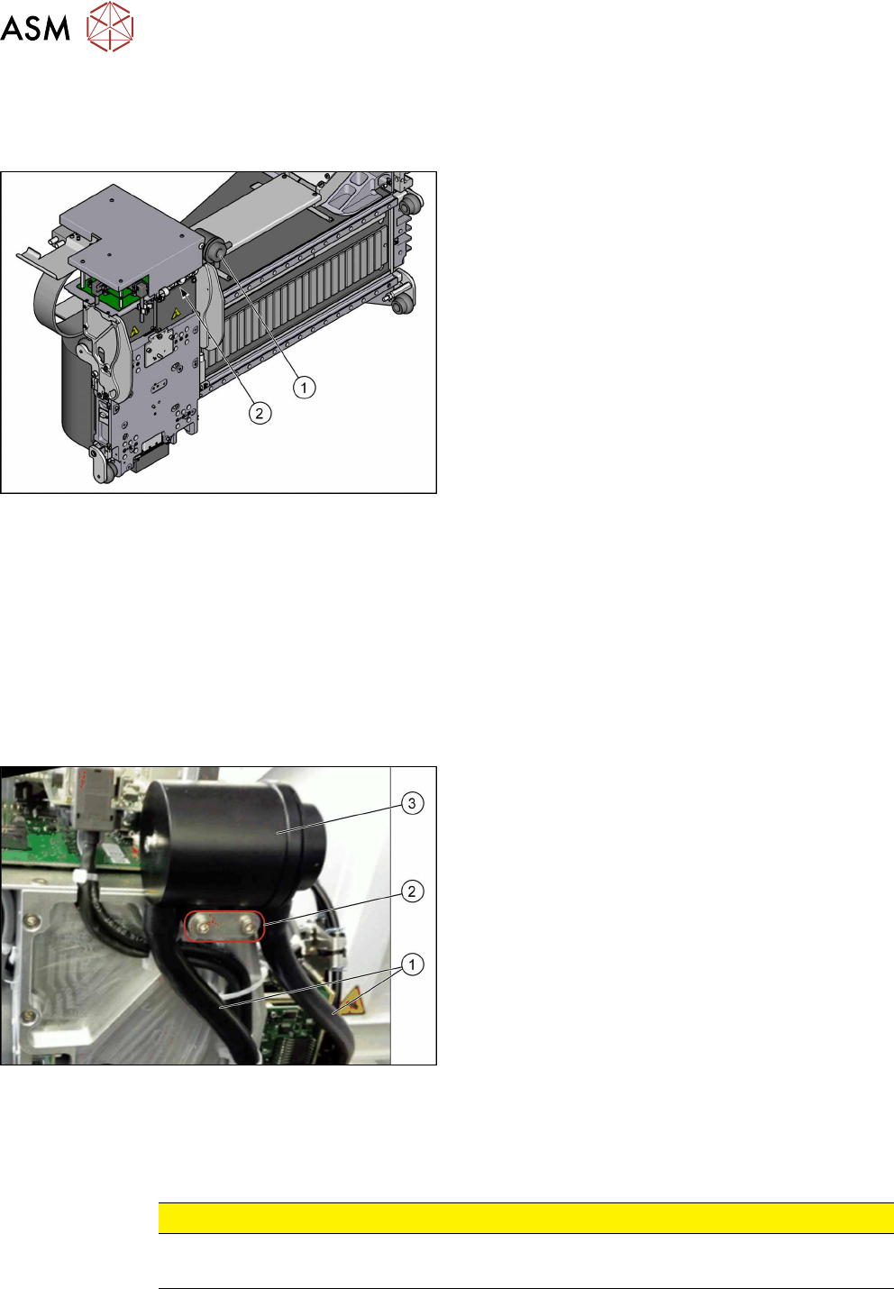
Fig.174: Filter and pneumatics
1. Cooling air filter
6.5.2 "Replacing the Cooling Air Filter [03018635-
xx]" [}132]
Replacing Filter Element / O-Ring
2. Pressure sensor vacuum
6.5.3 "Replacing Pressure Sensor Vacuum
[03108457-xx]" [}133]
6.5.2 Replacing the Cooling Air Filter [03018635-xx]
Parts, equipment and tools
●
Cooling air filter complete [03018635-xx]
●
Loctite 241 [02101037‑xx]
Removal
► Switch off the machine, disconnect it from the power supply and secure it to prevent
unauthorized reactivation. Observe the instructions in section 1.2 "Preparatory Work..." [}15].
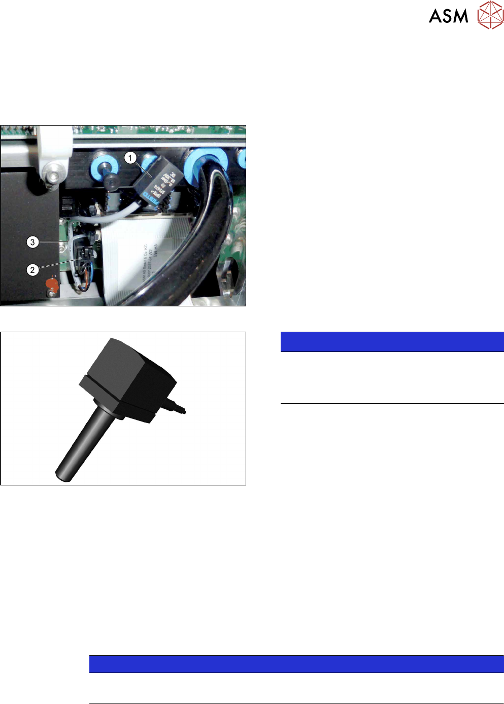
Fig.175: Cooling air filter
► Remove the two hoses(1).
► Remove the two screws(2) fastening the cooling
air filter (secured with Loctite 241).
► Remove the cooling air filter(3).
Installation
► Follow the removal instructions in reverse order for installation. Also observe the following in-
structions:
CAUTION
Installation instructions
► Secure screws with Loctite 241 where necessary.
6 Gantries
6.5 Filter and Pneumatics
Service Manual SIPLACE TX Series 06/2017 133
6.5.3 Replacing Pressure Sensor Vacuum [03108457-xx]
Parts, equipment and tools
●
Upgrade kit - pressure sensor for vacuum C&P20P [03108457‑xx]
Overview
Fig.176: Pressure sensor on the gantry
1. Pressure sensor
2. Connector on head adapter
3. Cable tie
The pressure sensor is located on the vacuum distrib-
utor of the gantry and is connected to the head ad-
apter.
Fig.177: Pressure sensor
NOTICE!
The pressure sensor is only needed when a va-
cuum pump and C&P20P heads are installed.
In this case, the pressure sensor is essential for
operation of the machine.
.
Removal
► Switch off the machine, disconnect it from the power supply and secure it to prevent
unauthorized reactivation. Observe the instructions in section 1.2 "Preparatory Work..." [}15].
► Loosen the electrical connection from the pressure sensor to the head adapter. You may want
to mark the position, to make clear assignment easier later on.
► Pull the pressure sensor off the vacuum distributor on the gantry.
Installation
► Follow the removal instructions in reverse order for installation. Also observe the following in-
structions:
NOTICE
Installation instructions
► Replace the cable ties which you removed before.