00198150-02_SM_TX_en.pdf - 第133页
6 Gantries 6.5 Filter and Pneumatics Service Manual SIPLACE TX Series 06/2017 133 6.5.3 Replacing Pressure Sensor Vacuum [03108457-xx] Parts, equipment and tools ● Upgrade kit - pressure sensor for vacuum C&P20P [03…
6 Gantries
6.5 Filter and Pneumatics
132 Service Manual SIPLACE TX Series 06/2017
6.5 Filter and Pneumatics
6.5.1 Gantries – Filter and Pneumatics – Overview
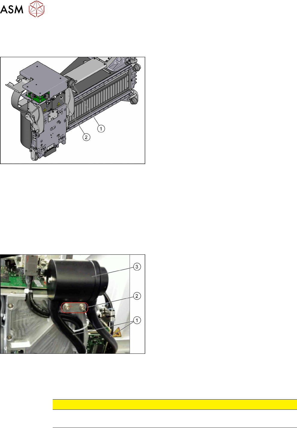
Fig.174: Filter and pneumatics
1. Cooling air filter
6.5.2 "Replacing the Cooling Air Filter [03018635-
xx]" [}132]
Replacing Filter Element / O-Ring
2. Pressure sensor vacuum
6.5.3 "Replacing Pressure Sensor Vacuum
[03108457-xx]" [}133]
6.5.2 Replacing the Cooling Air Filter [03018635-xx]
Parts, equipment and tools
●
Cooling air filter complete [03018635-xx]
●
Loctite 241 [02101037‑xx]
Removal
► Switch off the machine, disconnect it from the power supply and secure it to prevent
unauthorized reactivation. Observe the instructions in section 1.2 "Preparatory Work..." [}15].
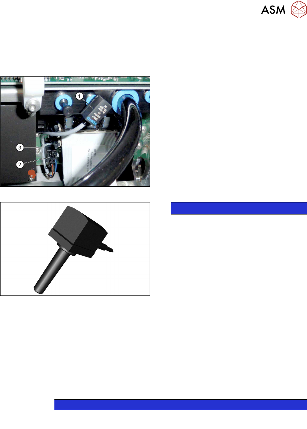
Fig.175: Cooling air filter
► Remove the two hoses(1).
► Remove the two screws(2) fastening the cooling
air filter (secured with Loctite 241).
► Remove the cooling air filter(3).
Installation
► Follow the removal instructions in reverse order for installation. Also observe the following in-
structions:
CAUTION
Installation instructions
► Secure screws with Loctite 241 where necessary.
6 Gantries
6.5 Filter and Pneumatics
Service Manual SIPLACE TX Series 06/2017 133
6.5.3 Replacing Pressure Sensor Vacuum [03108457-xx]
Parts, equipment and tools
●
Upgrade kit - pressure sensor for vacuum C&P20P [03108457‑xx]
Overview
Fig.176: Pressure sensor on the gantry
1. Pressure sensor
2. Connector on head adapter
3. Cable tie
The pressure sensor is located on the vacuum distrib-
utor of the gantry and is connected to the head ad-
apter.
Fig.177: Pressure sensor
NOTICE!
The pressure sensor is only needed when a va-
cuum pump and C&P20P heads are installed.
In this case, the pressure sensor is essential for
operation of the machine.
.
Removal
► Switch off the machine, disconnect it from the power supply and secure it to prevent
unauthorized reactivation. Observe the instructions in section 1.2 "Preparatory Work..." [}15].
► Loosen the electrical connection from the pressure sensor to the head adapter. You may want
to mark the position, to make clear assignment easier later on.
► Pull the pressure sensor off the vacuum distributor on the gantry.
Installation
► Follow the removal instructions in reverse order for installation. Also observe the following in-
structions:
NOTICE
Installation instructions
► Replace the cable ties which you removed before.
6 Gantries
6.6 Travel Ranges and Speed Monitoring
134 Service Manual SIPLACE TX Series 06/2017
6.6 Travel Ranges and Speed Monitoring
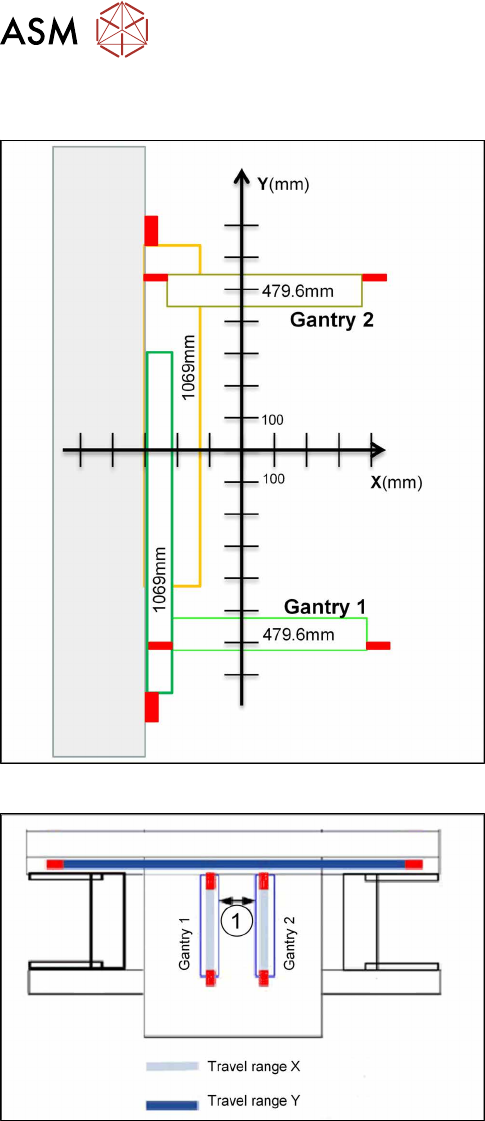
Fig.178: Travel ranges for X and Y axes
The travel range of the X and Y axes will be determ-
ined during machine calibration.
Travel range end of X axis
The end of the X axis travel range is + or - 0.2 mm be-
fore the software limit switch, which is 1.5 mm before
the buffer. A safety distance of 1.7 mm to the buffer is
adequate if the X axis moves into this area with ex-
cessive speed.
Travel range end of Y axis
The end of the Y axis travel range is + or - 2.0 mm be-
fore the software limit switch. The Y axis travel range
for a particular placement area is monitored in one dir-
ection by the software limit switch and a buffer. In the
other direction, there is a permanent exchange of
communication between the axes and their positions,
via the FDB bus.
Fig.179: Travel ranges for X and Y axes
1. Safety distance between the gantries during
placement: minimum 4mm.
Regardless of the placement mode (i-placement or al-
ternating), both gantries in one placement area only
move if they are referenced and if valid position in-
formation is available.