00198150-02_SM_TX_en.pdf - 第146页
7 Conveyor 7.3 Conveyor Drive 146 Service Manual SIPLACE TX Series 06/2017 7.3 Conveyor Drive 7.3.1 Replacing the Conveyor Drive Parts, equipment and tools ● Belt tension measuring device [00326015‑xx] Fig.197: Conveyor…
7 Conveyor
7.2 Lifting Table
Service Manual SIPLACE TX Series 06/2017 145
7.2.6 Calibrating the Lifting Table Motor
After completing the work on the lifting table, this will need to be calibrated.
Procedure
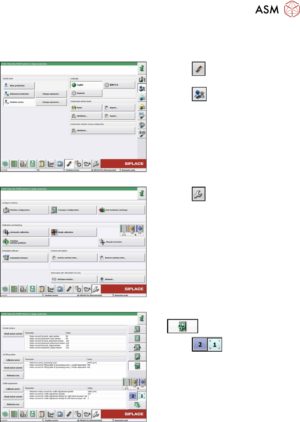
Fig.194: Select operator level
► Click the
button to enter the Settings
menu.
► Click the
button to open the Check and set
user settings menu.
► Switch to operator level Machine service or bet-
ter.
Fig.195: Service menu
► Click the
button to open the Service menu.
► Select Conveyor configuration.
Fig.196: Conveyor menu
► Click the Initiate conveyor parameters
button.
► Click the
buttons to select the re-
quired conveyor lane.
► Go to the All lifting tables section and select the
Calibrate motor button.
► Check the clamps (distance between clamping
plate and clamping rail) and adjust if necessary
(see 7.2.4 "Setting the Parallelism and Height of
the Lifting Table Plate" [}143]).
7 Conveyor
7.3 Conveyor Drive
146 Service Manual SIPLACE TX Series 06/2017
7.3 Conveyor Drive
7.3.1 Replacing the Conveyor Drive
Parts, equipment and tools
●
Belt tension measuring device [00326015‑xx]
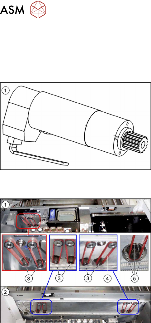
Fig.197: Conveyor drive
1. DC drive motor with synchronizing disk SXa
[03093387‑xx]
Overview
Fig.198: Conveyor drives and toothed belts
1. Conveyor drives in lane 1 (location 1)
2. Conveyor drives in lane 2 (location 2)
3. Six conveyor drives
4. Toothed belt for conveyor drives
5. Three screws fastening the conveyor drives
7 Conveyor
7.3 Conveyor Drive
Service Manual SIPLACE TX Series 06/2017 147
Removal
► Use the software or manually move the conveyor rail into a position which allows you best ac-
cess.
– To move the conveyor rail manually, pull the toothed belt of the width adjustment unit.
► Switch off the machine, disconnect it from the power supply and secure it to prevent
unauthorized reactivation. Observe the instructions in section 1.2 "Preparatory Work..." [}15].
► Move all gantries out of the transport area as far as possible at one side of the machine.
► The fastening screws of the conveyor drives are on the outer side of the conveyor. You may
have to move out the COTi to get access to these screws. In this case follow the instructions
to move out the COTi.
Replacing the COTi Central Unit and Lifting Mechanics [}235]
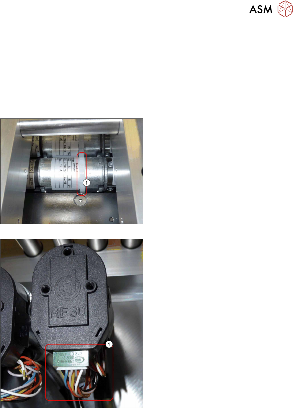
Fig.199: Cable tie
► Remove the cable tie(1) around the conveyor
drive.
Fig.200: Electrical connections
► Unplug all electrical connections from the con-
veyor drive(1). You may want to mark their posi-
tions for easier exact replacement later on.