00198150-02_SM_TX_en.pdf - 第156页
7 Conveyor 7.4 Width Adjustment 156 Service Manual SIPLACE TX Series 06/2017 Fig.210: Service menu ► Click the button to open the Service menu. ► Click on the Conveyor Configuration button. Fig.211: Conveyor menu ► Cli…
7 Conveyor
7.4 Width Adjustment
Service Manual SIPLACE TX Series 06/2017 155
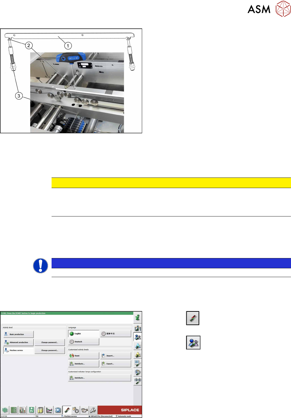
Fig.208: Removing clamping plate
► Insert the small pin or Allen key(3) to fix the actu-
ator.
► Remove the two screws(2) fastening clamping
plate(1).
First loosen one screw lightly, and then loosen
the other screw lightly.
► Remove inserted Allen key and remove the actu-
ator from bottom side.
►
Remove the clamping plate(1) with two fastening
screws carefully.
Installation
► Follow the removal instructions in reverse order for installation. Also observe the following in-
structions:
CAUTION
Installation instructions
► Tighten the fastening screws (2) with a torque of 1.45 Nm (NO loctite).
► Remove the pin (3).
7.4.3 Calibrating the Adjustment Unit
NOTICE
This chapter is valid for machines with dual conveyor (DC) only.
After completing all work to the width adjustment (adjustment unit, motor or belt of width adjust-
ment), you need to configure the adjustment unit before you configure the conveyor sides.
Procedure
Fig.209: Select operator level
► Click the
button to enter the Settings
menu.
► Click the
button to open the Check and set
user settings menu.
► Switch to operator level Machine service or bet-
ter.
7 Conveyor
7.4 Width Adjustment
156 Service Manual SIPLACE TX Series 06/2017
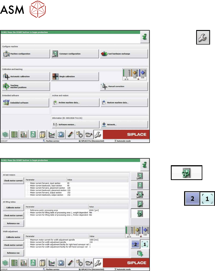
Fig.210: Service menu
► Click the
button to open the Service menu.
► Click on the Conveyor Configurationbutton.
Fig.211: Conveyor menu
► Click on the Initiate conveyor parameters
button.
► Select the required conveyor lane with the but-
tons
.
► Go to the section Width adjustment and select
the button Calibrate motor.
7 Conveyor
7.4 Width Adjustment
Service Manual SIPLACE TX Series 06/2017 157
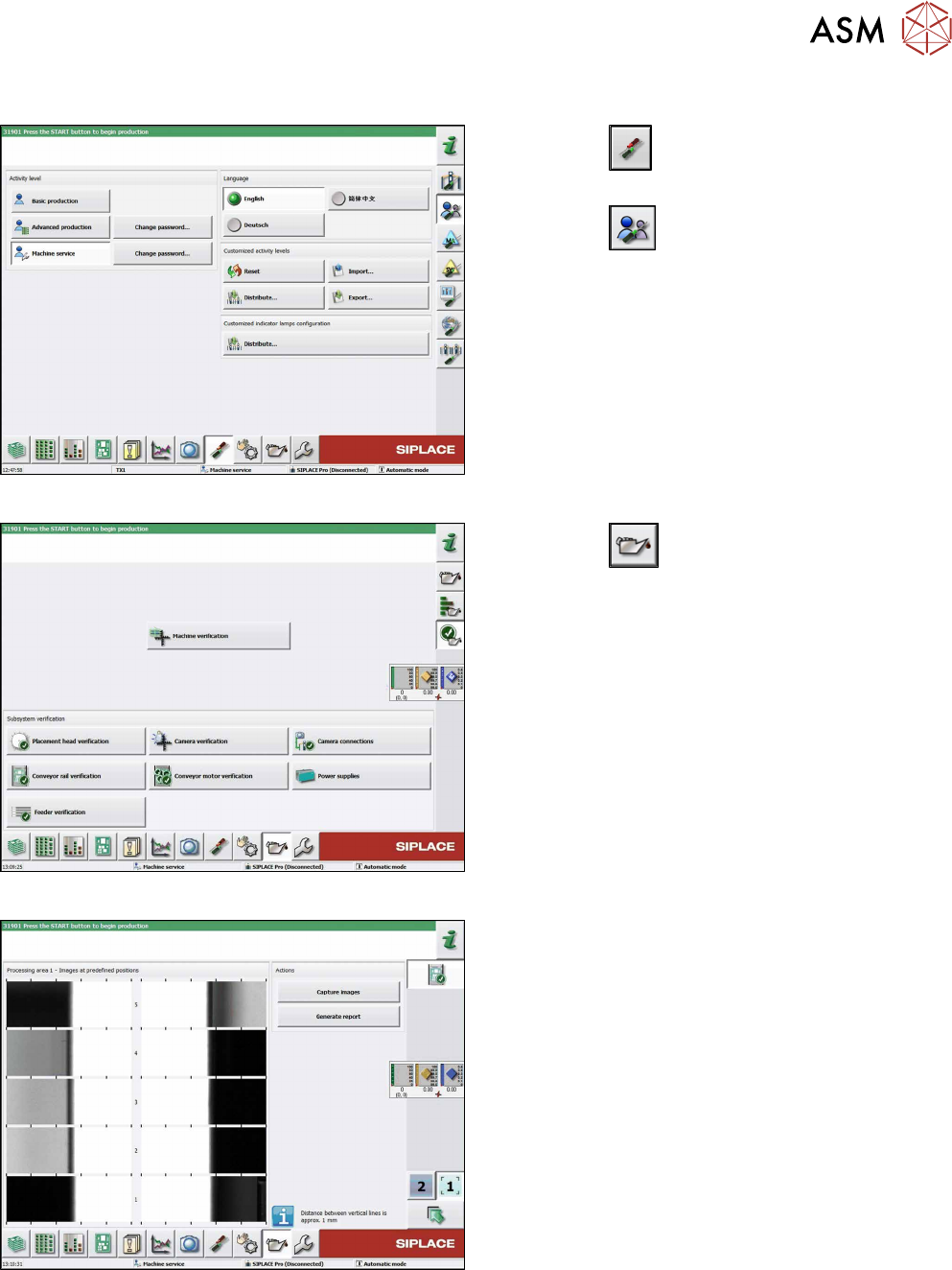
7.4.4 Setting the Parallelism of the Adjustment Units for Dual Conveyors
Fig.212: Select operator level
► Click the
button to enter the Settings
menu.
► Click the
button to open the Check and set
user settings menu.
► Switch to operator level Machine service or bet-
ter.
Fig.213: Maintenance menu
► Click the
button to enter the maintenance
menu..
► Click the Conveyor rail verification button.
Fig.214: Conveyor rail verification
► Click the Capture images button to start test.