00198150-02_SM_TX_en.pdf - 第158页
7 Conveyor 7.5 Conveyor Belt, Belt Drive and Hexagonal Shaft 158 Service Manual SIPLACE TX Series 06/2017 7.5 Conveyor Belt, Belt Drive and Hexagonal Shaft 7.5.1 Replacing the Toothed Belt (Conveyor Belt) Parts, equipmen…
7 Conveyor
7.4 Width Adjustment
Service Manual SIPLACE TX Series 06/2017 157
7.4.4 Setting the Parallelism of the Adjustment Units for Dual Conveyors
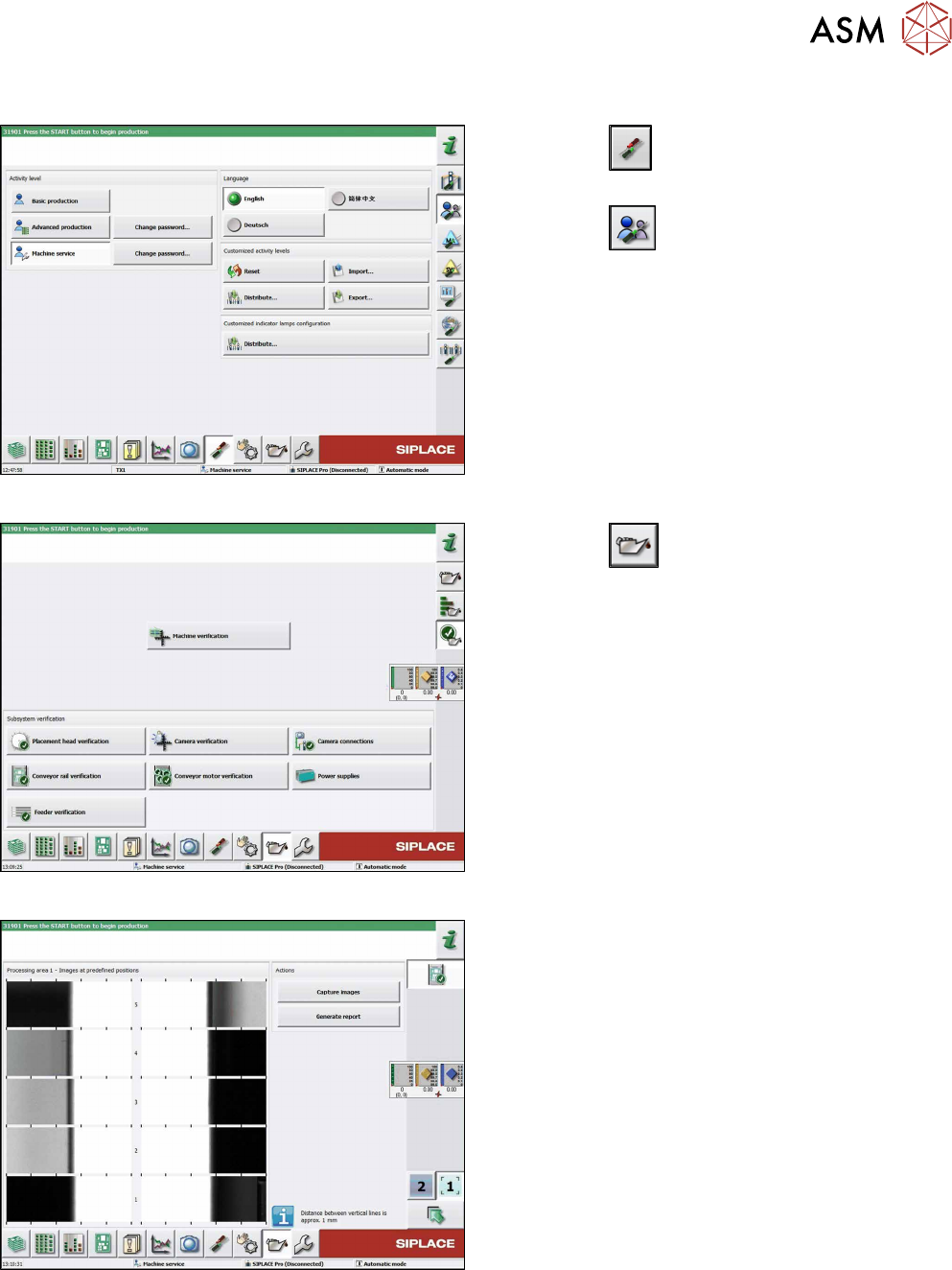
Fig.212: Select operator level
► Click the
button to enter the Settings
menu.
► Click the
button to open the Check and set
user settings menu.
► Switch to operator level Machine service or bet-
ter.
Fig.213: Maintenance menu
► Click the
button to enter the maintenance
menu..
► Click the Conveyor rail verification button.
Fig.214: Conveyor rail verification
► Click the Capture images button to start test.
7 Conveyor
7.5 Conveyor Belt, Belt Drive and Hexagonal Shaft
158 Service Manual SIPLACE TX Series 06/2017
7.5 Conveyor Belt, Belt Drive and Hexagonal Shaft
7.5.1 Replacing the Toothed Belt (Conveyor Belt)
Parts, equipment and tools
●
Belt tension measuring device [00326015‑xx]
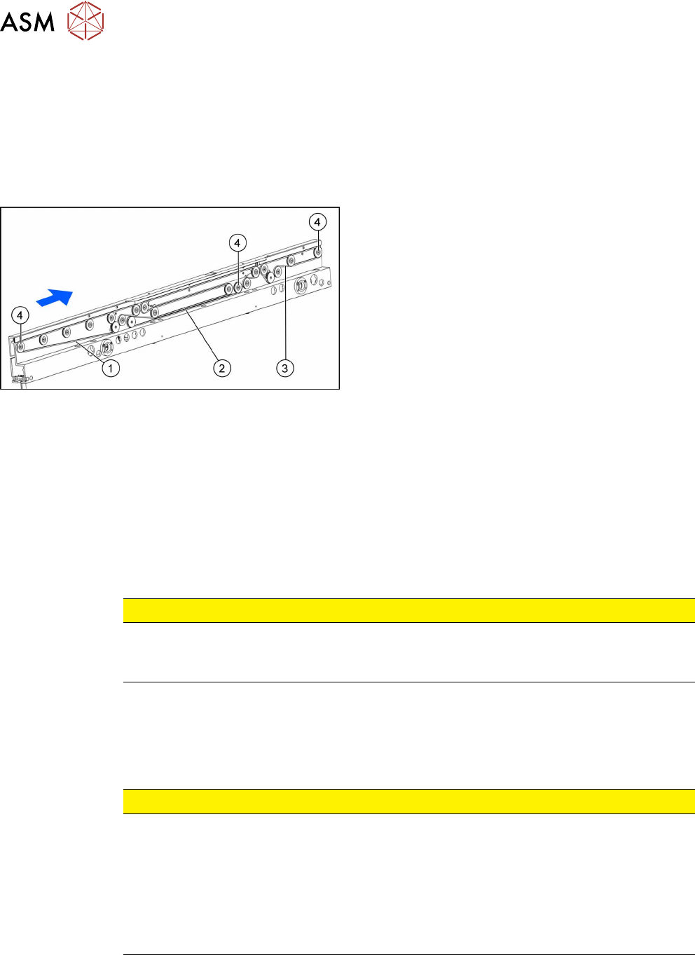
Select the required toothed belt:
Fig.215: Toothed belts
1. Input area:
Synchronous belt L=843 mm [03121441‑xx]
2. PA:
Synchronous belt L=843 mm [03121441‑xx]
3. Output area:
Synchronous belt L=447 mm [03121443‑xx]
4. Movable idler pulleys
Removal
► Use the software or manually move the conveyor rail into a position which allows you best ac-
cess.
– To move the conveyor rail manually, pull the toothed belt of the width adjustment unit.
► Switch off the machine, disconnect it from the power supply and secure it to prevent
unauthorized reactivation. Observe the instructions in section 1.2 "Preparatory Work..." [}15].
► Move all gantries out of the transport area as far as possible at one side of the machine.
► Loosen the movable idler pulley.
CAUTION
Loosen the movable idler pulley only as far as necessary!
► Do not remove the movable idler pulley. Otherwise the T-slot nut on the inner side will
fall into the conveyor rail.
► Carefully unthread the belt drive.
Installation
► Follow the removal instructions in reverse order for installation. Also observe the following in-
structions:
CAUTION
Installation instructions
► Check the new toothed belt before fitting it. Hold it up high. It should hang loose and
should not twist.
► Do not bend or damage the toothed belt.
► Make sure that the toothed belt is positioned accurately in the guidance on the motor
shaft or in the belt drive.
► When you tighten the idler pulley, set the tension of the toothed belt (see below).
See also
2 Setting the Tension of the Conveyor Toothed Belt [}159]
2 Belt Tension [}159]
7 Conveyor
7.5 Conveyor Belt, Belt Drive and Hexagonal Shaft
Service Manual SIPLACE TX Series 06/2017 159
7.5.2 Belt Tension
The precalculated values for setting the belt tension can be found in the following chapters.
In addition, the value for any section of the conveyor belt can be calculated using a formula
(see 7.5.2.2 "Calculating the Belt Tension" [}160]).
7.5.2.1 Setting the Tension of the Conveyor Toothed Belt
Parts, equipment and tools
●
Belt tension measuring device [00326015‑xx]
If the input/output extension option is installed:
●
Assembly instructions "Input/output extension option – SIPLACE TX‑Series" [DE
+EN:00198141‑xx]
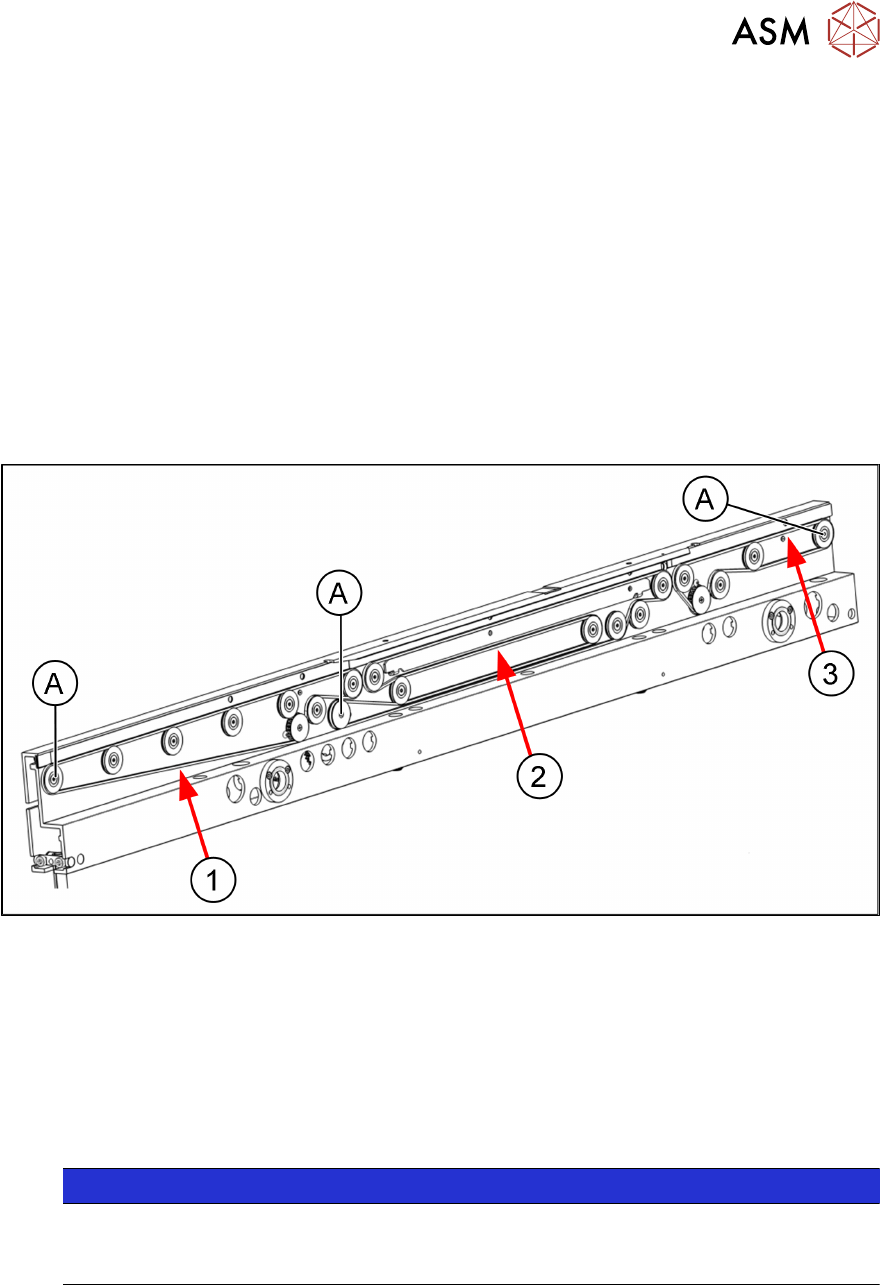
Overview of measuring points and values
Fig.216: Measuring points
A Movable idler pulleys
1 Measuring point on the toothed belt in the input area 49 +/- 5 Hz
2 Measuring point on the toothed belt in the placement area 62 +/- 5 Hz
3 Measuring point on the toothed belt in output area 170 +/- 10 Hz
Adjustment
NOTICE
Pulling out the COT insert
To gain better access to the various screws, you may need to pull the COT insert out a
little.
Replacing the COTi Central Unit and Lifting Mechanics [}235]
► Use the software or manually move the conveyor rail into a position which allows you best ac-
cess.
– To move the conveyor rail manually, pull the toothed belt of the width adjustment unit.
► Switch off the machine, disconnect it from the power supply and secure it to prevent
unauthorized reactivation. Observe the instructions in section 1.2 "Preparatory Work..." [}15].
► Move all gantries out of the transport area as far as possible at one side of the machine.