00198150-02_SM_TX_en.pdf - 第168页
7 Conveyor 7.6 Fiber Optic Cable and Light Barriers 168 Service Manual SIPLACE TX Series 06/2017 ► Use the button to select the required conveyor lane. Fig.229: Checking function of the laser light ► Check the function …
7 Conveyor
7.6 Fiber Optic Cable and Light Barriers
Service Manual SIPLACE TX Series 06/2017 167
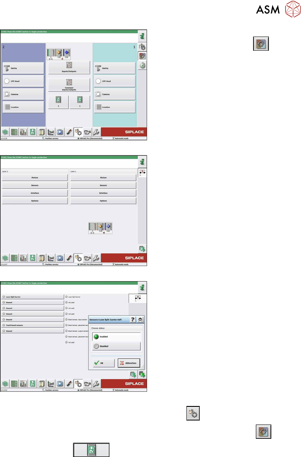
Fig.226: Check sensors and functions
► Click on the button Check sensors and func-
tions of specific components
.
► Click on the Conveyor inputs/outputsbutton.
Fig.227: Inputs/outputs
► Click on the button Sensors.
Fig.228: Sensors
► Enable the Laser light barrier button.
► Click on the button Check sensors and functions
.
► Click on the button Check sensors and functions of specific components
.
► Click the
button.
7 Conveyor
7.6 Fiber Optic Cable and Light Barriers
168 Service Manual SIPLACE TX Series 06/2017
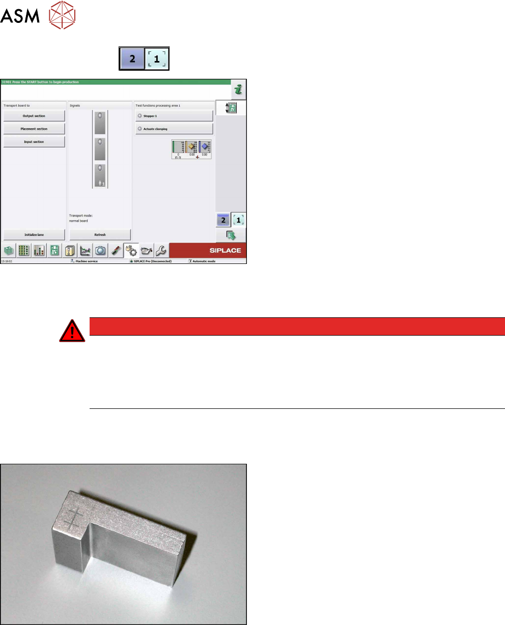
► Use the
button to select the required conveyor lane.
Fig.229: Checking function of the laser light
► Check the function of the laser light barrier. To do
this, move a board through the conveyor.
► Correct the laser light barrier setting, if necessary
(see Correcting the Laser Light Barrier Setting).
7.6.3 Correcting the Laser Light Barrier Setting
DANGER
Laser class 2
The laser light barrier transmitter emits class 2 laser beams. You therefore do not require
additional protective measures!
► However, you should never look into the laser beam.
► Adjust the laser beam only from the rear side of the laser!
Parts, equipment and tools
●
Recommendation for new version of receiver (silver receiver surface):
Semi-transparent paper or plastic (for better recognition of laser beam)
Fig.230: Setting gauge
Optional:
●
Setting gauge for conveyor laser light barrier
[00369205-xx]
7 Conveyor
7.6 Fiber Optic Cable and Light Barriers
Service Manual SIPLACE TX Series 06/2017 169
Overview
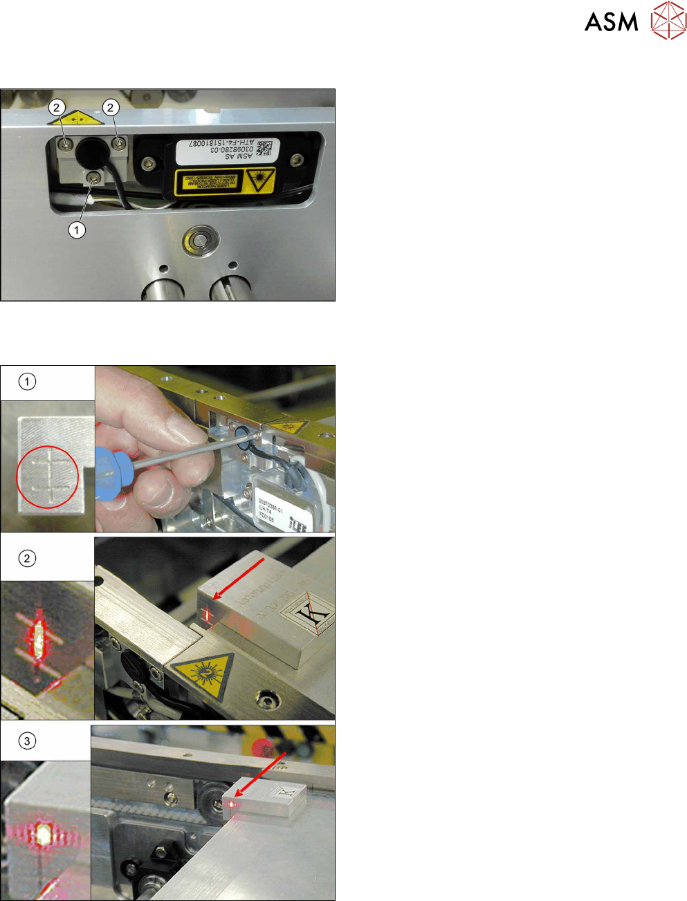
Fig.231: Laser light barrier
1. Fastening screw
2. Setting screws
Procedure with setting gauge
Fig.232: Focusing the laser beam (using example of X-Series)
1. Setting the laser light barrier
2. Minimum width
3. Maximum width
► Set the maximum conveyor width.
► Select Enable safety mode in software.
► Activate the relevant laser diode using the input/
output functions in the station software.
► Check the path of the laser beam with the help of
the gauge.
► With the help of the three setting screws, adjust
the laser beam to the center of the gauge cross
(1).
► Now position the conveyor to minimum width(2)
and check the setting.
► Check the PCB reference corner and reteach, if
necessary.