00198150-02_SM_TX_en.pdf - 第171页
7 Conveyor 7.6 Fiber Optic Cable and Light Barriers Service Manual SIPLACE TX Series 06/2017 171 Parts, equipment and tools ● Fiber optic cable LL3-TV05 2 m [03092407-xx] ● Fiber optic cable LL3-TV05 3 m [03092408-xx] (s…

7 Conveyor
7.6 Fiber Optic Cable and Light Barriers
170 Service Manual SIPLACE TX Series 06/2017
Procedure without setting gauge
► Set the maximum conveyor width.
NOTICE
Deviation of the laser beam has the greatest effect at maximum conveyor width
► Select "Enable safety mode".
► Activate the relevant laser diode using the input/output functions in the station software.
► Use the top two screws to set the laser beam so that it is correctly aligned with the laser recei-
ver.
CAUTION
Screws on the laser transmitter
► Hand-tighten the lower screw. The top two screws are used to set the laser beam.
These may not be fully tightened, otherwise the laser transmitter could be damaged.
NOTICE
Semi-transparent paper or plastic
► Use semi-transparent paper or plastic to make the laser beam visible on the receiver.
► Now position the conveyor to minimum width and check the setting.
► Check the PCB reference corner and reteach, if necessary.
7.6.4 Repairing the Fiber Optic Cable
To avoid machine downtimes, it is possible to repair fiber optic cables temporarily, using the repair
hose.
NOTICE
Repair hose for fiber optic cable LL3-TV05
► The repair hose may only be used for short periods to avoid machine downtimes.
► The repair hose may only be used once per fiber optic cable.
► The fiber optic cable must be replaced during the next repair or maintenance cycle.
NOTICE
No guarantee
► No guarantee is given if the fiber optic cable is repaired using the repair hose.
► There is no long-term experience with the repair hose.
► Depending on the board width, the intensity of the light beam may diminish in such a
way that an evaluation is no longer possible.
► The repair hose must not be bended. For this reason, there is an additional danger of
rupture after the repair, in areas where the fiber optic cable is routed in narrow radii.
If there is another rupture of the fiber optic cable and no complete replacement is possible, proceed
as follows:
► Replace the defective part of the fiber optic cable in such a way that only one repair hose is
used.

7 Conveyor
7.6 Fiber Optic Cable and Light Barriers
Service Manual SIPLACE TX Series 06/2017 171
Parts, equipment and tools
●
Fiber optic cable LL3-TV05 2 m [03092407-xx]
●
Fiber optic cable LL3-TV05 3 m [03092408-xx] (spare part)
●
Cutter tool for the fiber optic cable (supplied in the scope of delivery)
●
Hose PUN 3x0.5SW, 100mm [03122383-xx] (repair hose)
A repair hose is supplied with each fiber optic cable. The repair hose is not available as an in-
dividual spare part.
●
Sheet with yellow glue dots
●
Loctite 406 [03017821-xx] (instant glue highly viscous)
●
Dosage tip for Loctite [03019481-xx]
●
Protective latex gloves [00372972-xx]
Troubleshooting
► In the station software, activate all fiber optic cables (transmitters). These may need to be re-
calibrated without boards in the conveyor.
► A red light must be visible for the transmitters.
If no light is visible at the transmitter, there is probably an error.
► As a cross-check, you can switch the transmitting and receiving fiber optic cable at the corres-
ponding fiber optic sensor (WLL180T-F preconfigured SXa [03093295‑xx] or WLL180T-M pre-
configured SXa [03093294‑xx]).
Replacing the Fiber Optic Cable Sensor [}174]
NOTICE
Do not confuse the transmitter with the receiver
► Make sure not to confuse the transmitting and receiving fiber optic cable. If you do,
other optical sensors may be sporadically affected.
NOTICE
Display on the fiber optic sensors
The display on the fiber optic sensors corresponds to the currently measured intensity.
► The intensity can vary depending on installation position, cable length and environ-
mental conditions.
► The value shown should be not less than 100.
► The sensor reacts to intensity deviations during operation.
7 Conveyor
7.6 Fiber Optic Cable and Light Barriers
172 Service Manual SIPLACE TX Series 06/2017
Performing the repair
► Use the software or manually move the conveyor rail into a position which allows you best ac-
cess.
– To move the conveyor rail manually, pull the toothed belt of the width adjustment unit.
► Switch off the machine, disconnect it from the power supply and secure it to prevent
unauthorized reactivation. Observe the instructions in section 1.2 "Preparatory Work..." [}15].
► Move all gantries out of the transport area as far as possible at one side of the machine.
► Remove the fiber optic cable from the conveyor side.
NOTICE
Sticker
If the fiber optic cable has already been repaired, a yellow adhesive sticker dot will be at-
tached to the optical system or the analysis unit.
You may only use one repair hose per fiber optic cable. You must either replace the whole
fiber optic cable or the part that has already been repaired.
► Check the fiber optic cable for damages.
The most common error causes are:
– Damaged optical system of the fiber optic cable
– Fiber optic cable pinched in conveyor side
– Ruptured fiber optic cable (e.g. caused by a too narrow bending radius)
NOTICE
Fiber optic cable ruptured at the trailing chain
If the fiber optic cable is ruptured in the trailing chain or at the transition from the trailing
chain to the conveyor side, the effort for finding the error cause is often identical to the ef-
fort for replacing the complete fiber optic cable.
► Cut the fiber optic cable at the defective position.
► Use the cutter tool to cut off 10mm of the fiber optic cable on each side of the rupture.
Make sure to preserve a minimum distance of approx. 50mm to the optical system.
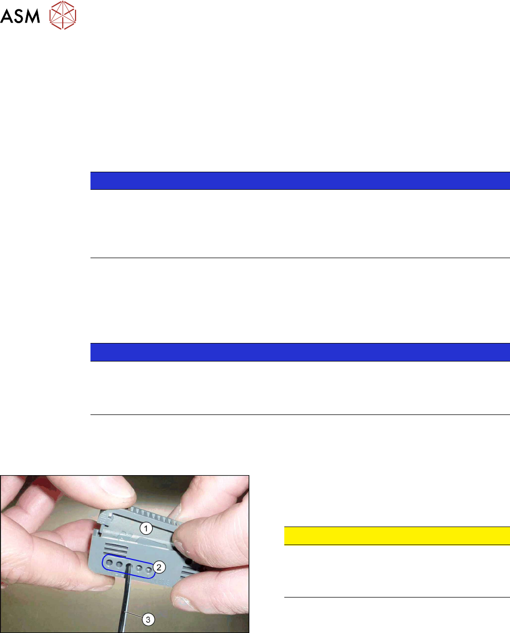
Fig.233: Cutter tool
1. Cutter tool
2. Cutting aperture
3. Fiber optic cable
CAUTION!
Only use each cutting aperture once
Make sure that you only use each cutting aper-
ture once. If they are used more than once, good
quality cuts can not be guaranteed.
.