00198150-02_SM_TX_en.pdf - 第177页
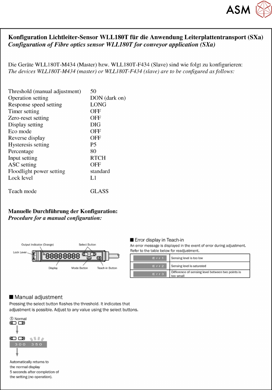
7 Conveyor 7.6 Fiber Optic Cable and Light Barriers Service Manual SIPLACE TX Series 06/2017 177 Fig.238: Setting the fiber optic cable sensor - 1

7 Conveyor
7.6 Fiber Optic Cable and Light Barriers
176 Service Manual SIPLACE TX Series 06/2017
Installation
► Follow the removal instructions in reverse order for installation. Also observe the following in-
structions:
CAUTION
Installation instructions
► Check the setting on the fiber optic sensor and correct if necessary (see following sec-
tion).
New sensors are preset.
► Remove the plastic cover for the sensor on the side press-fit connections, if needed.
► Teach the PCB sensors.
See also
2 Setting the Fiber Optic Cable Sensor [}176]
7.6.5.1 Setting the Fiber Optic Cable Sensor
The brightness of the sensors changes according to the positions of the conveyor sides. For this
reason, the sensors are automatically recalibrated after each automatic adjustment of the conveyor
sides.
If the conveyor sides are manually adjusted, there will be no automatic calibration. In this case, cal-
ibration needs to be manually triggered in the Service menu. Without this calibration, the station
software will show boards which are not physically present.
You can check the correct calibration on the sensor modules.
●
Red display: current signal strength of receiver
●
Green display: reference value of receiver
A board is recognized if the value in the red display is smaller than the value in the green display.
Without a board, the value of the green display must be 10 to 20% smaller than the value of the
red display.
During calibration, the reference value (green display) is automatically set to a lower value than the
current signal strength (red display). It is assumed that there is no board in the sensor range at this
moment.
The absolute sensor value is not significant. This can vary between sensor modules.
NOTICE
No board in conveyor
When calibrating the light barriers make sure that there is no board in the conveyor.
7 Conveyor
7.6 Fiber Optic Cable and Light Barriers
Service Manual SIPLACE TX Series 06/2017 177
Fig.238: Setting the fiber optic cable sensor - 1
7 Conveyor
7.6 Fiber Optic Cable and Light Barriers
178 Service Manual SIPLACE TX Series 06/2017
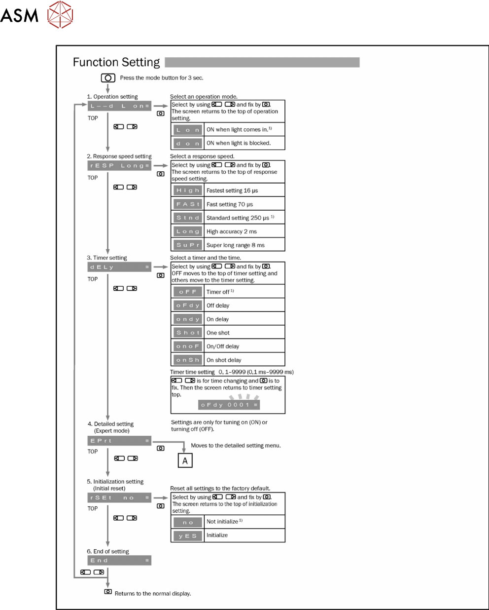
Fig.239: Setting the fiber optic cable sensor - 2